N9030B PXA Signal Analyzer Service Guide 497
Assembly Replacement Procedures
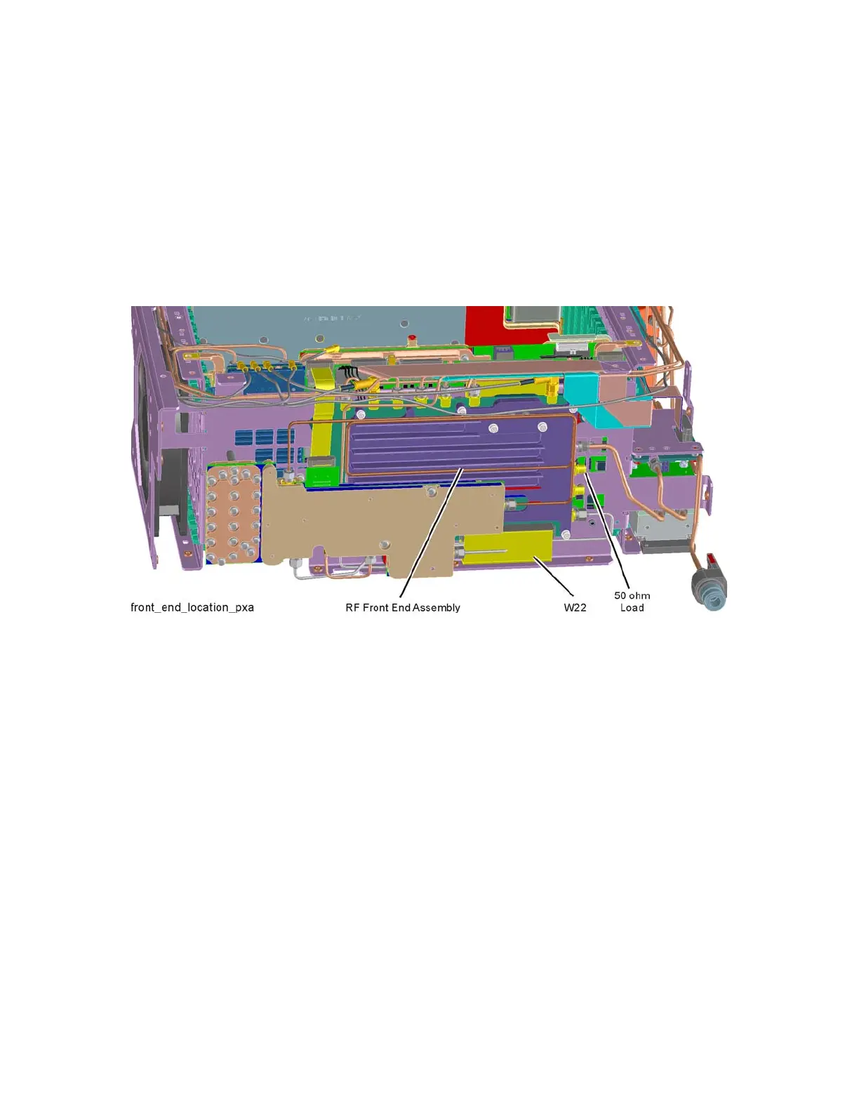
RF Front End Assembly
Replacement
1. Refer to Figure 16-64. Attach the W22 ribbon cable to the Front End
Assembly first. Route behind the Front End Assembly and ensure the cable
is engaged under the tabs, then place the RF Front End Assembly into the
chassis. If you are replacing the Front End Assembly make sure to reinstall
the 50 ohm load onto A13A1J8 if the analyzer does not have Option EXM.
Torque to 10 inch-pounds.
Figure 16-64 RF Front End Assembly Location
2. Refer to Figure 16-62. Replace the six screws (1) (0515-0372). Torque to
9 inch-pounds in the sequence shown, starting with #1.
3. Reattach W22 ribbon cable to Front End Controller J102 and W28 ribbon
cable between Front End Controller J1300 and A13A2J1 on the RF Front
End Assembly.
4. Reattach the cables to A13A1J1, A13A1J2, A13A1J4, A13A1J5, A13A1J6,
A13A1J7, and A13A1J9 on the RF Front End Assembly. Reattach the
cables to A13A1J8 and A13A1J13 if Option EXM is present. Torque the
semi-rigid cables to 10 inch-pounds.
5. Replace the front panel. Refer to the Front Frame Assembly replacement
procedure.
6. Replace the instrument top brace. Refer to the Top Brace and Power
Supply Bracket replacement procedure.
7. Replace the instrument outer case. Refer to the Instrument Outer Case
replacement procedure.