N9030B PXA Signal Analyzer Service Guide 451
Assembly Replacement Procedures
RF Area (Options 503, 508, 513, 526)
Options MPB and LNP
Removal
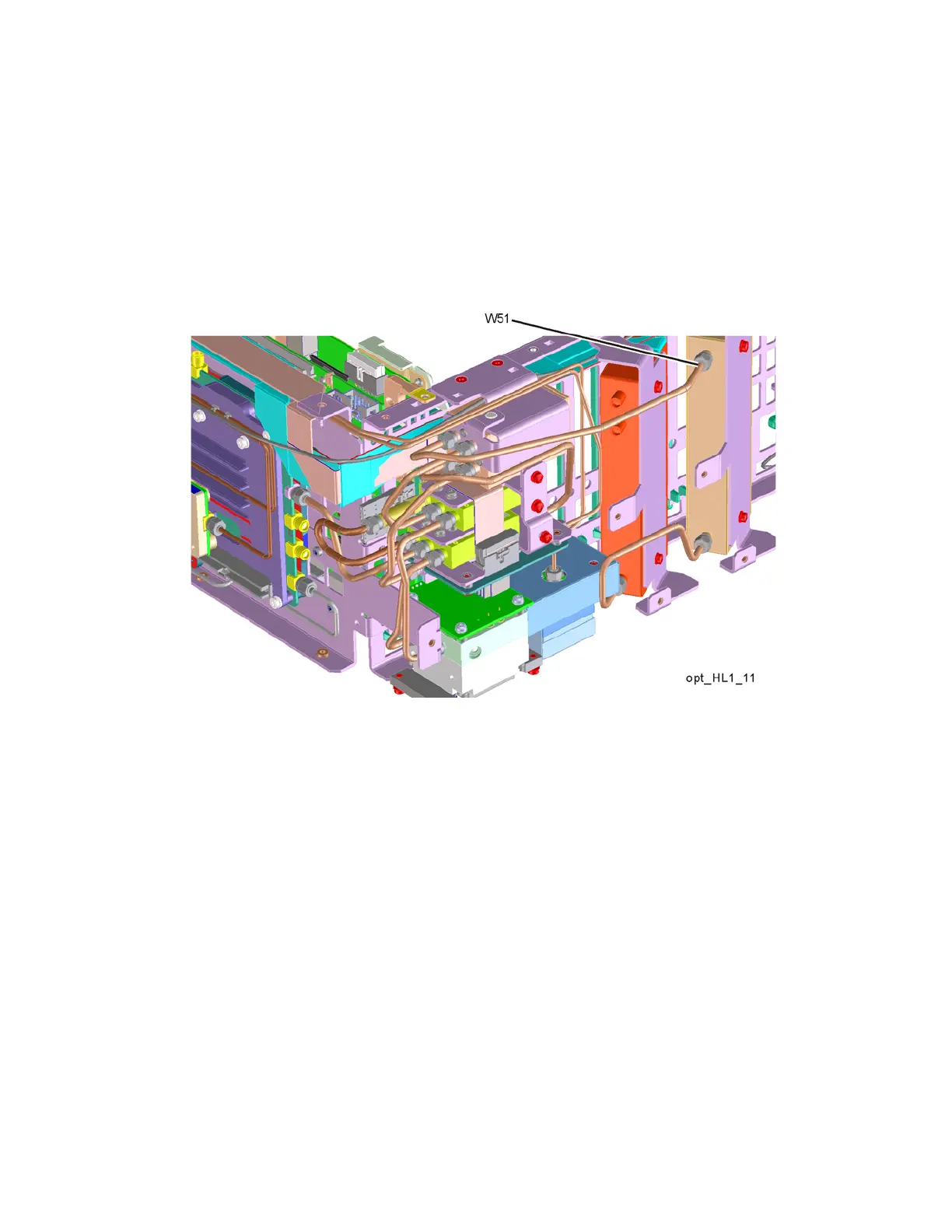
1. Refer to Figure 16-17. Remove rigid cable W51 (N9020-20143) from top
switch port 1 to Attenuator B output.
Figure 16-17 W51 Cable Removal