452 N9030B PXA Signal Analyzer Service Guide
Assembly Replacement Procedures
RF Area (Options 503, 508, 513, 526)
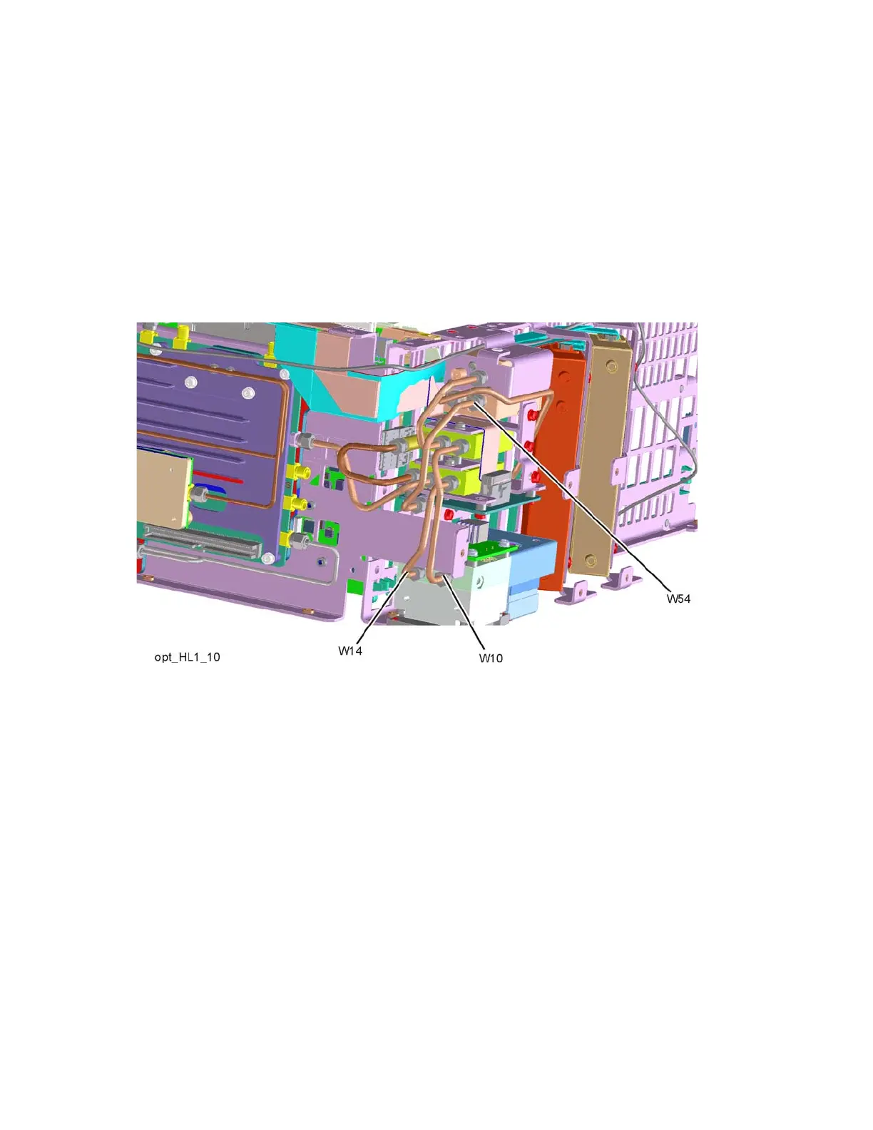
2. Refer to Figure 16-18. Remove cable W10 (E4410-20163) from middle
switch port 2 to YTF Assembly.
3. Remove cable W14 (E4410-20165) from bottom switch port 2 to YTF
Assembly.
4. Remove cable W54 (N9020-20145) from top switch port 3 to Low Band
Switch Assembly.
Figure 16-18 W10, W14, and W54 Cables Removal
 Loading...


