436 N9030B PXA Signal Analyzer Service Guide
Assembly Replacement Procedures
Top Brace and Power Supply Bracket
Top Brace and Power Supply Bracket
Removal
1. Remove the instrument outer case. Refer to the Instrument Outer Case
removal procedure.
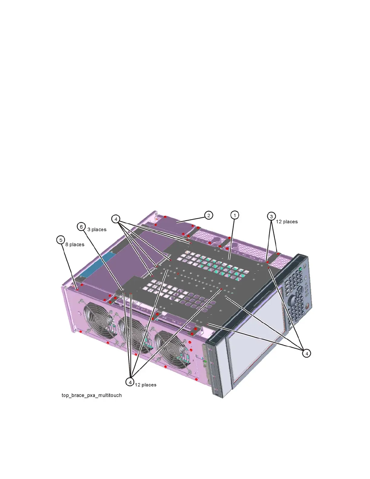
2. Refer to Figure 16-4. To remove the top brace (1), use the T-10 driver to
remove the twelve screws (3) (0515-0372) attaching the top brace to the
chassis. Remove the wire hold down 1 (as shown in Figure 16-5). Remove
the twelve screws (14 screws with Option B1X) (4) (0515-1946) attaching
the top brace to the boards.
3. To remove the power supply bracket (2), use the T-10 driver to remove
the eight screws (5) (0515-0372) attaching the power supply bracket to
the instrument and the three screws (6) (0515-1946) attaching the power
supply bracket to the power supply.
Figure 16-4 Top Brace and Power Supply Bracket Removal