438 N9030B PXA Signal Analyzer Service Guide
Assembly Replacement Procedures
RF Area (Options 503, 508, 513, 526)
RF Area (Options 503, 508, 513, 526)
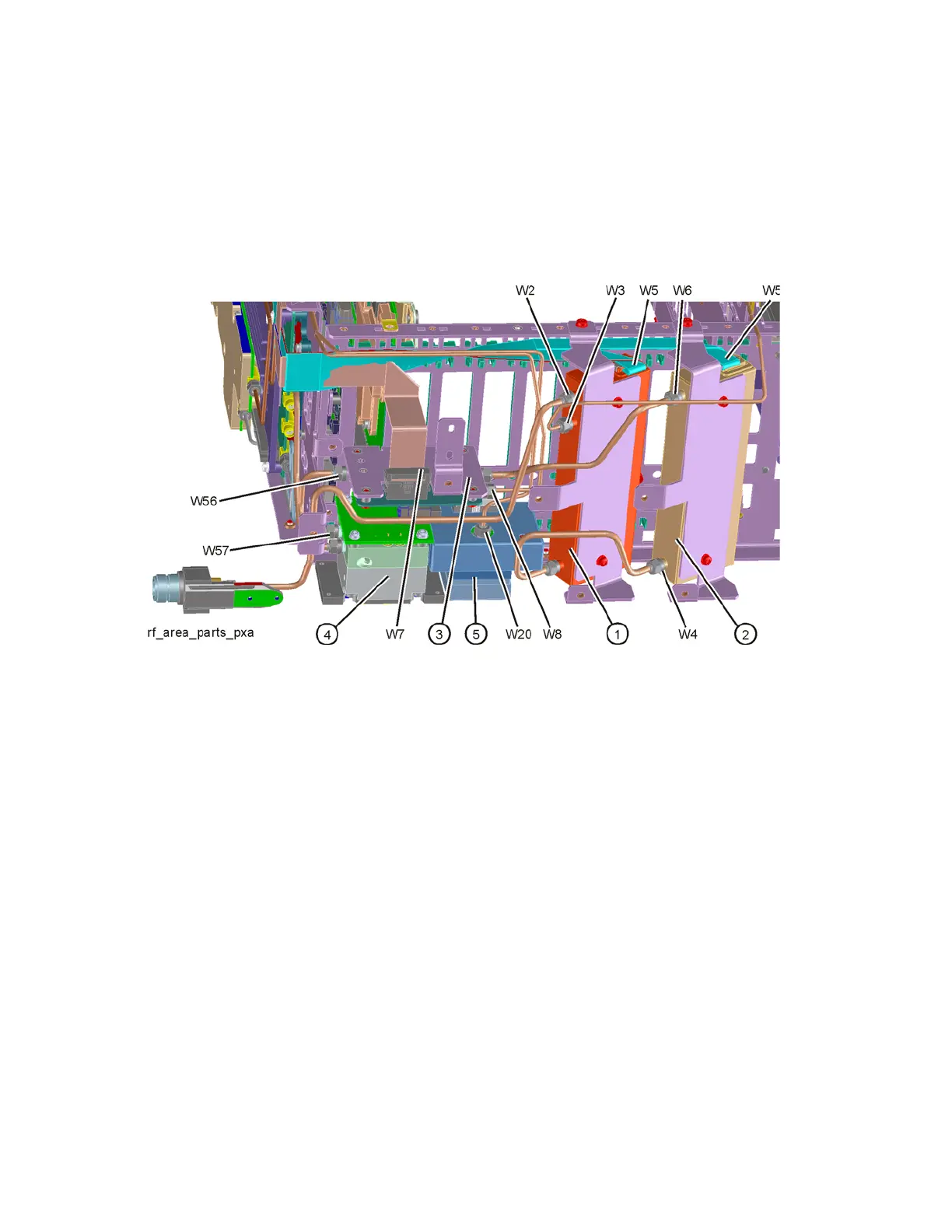
Refer to Figure 16-6. The RF area consists of RF attenuator A (1), RF
attenuator B (2), low band switch assembly (3), YTF Preselector (4), and YTO
(5).
Figure 16-6 RF Area Components and Cables
(Options 503, 508, 513, 526)
To gain access to the attenuators, low band switch, YTF Preselector, YTO,
Option MPB, or Option LNP for removal, follow these steps:
1. Remove the instrument outer case. Refer to the Instrument Outer Case
removal procedure.
2. Remove the front panel. Refer to the Front Frame Assembly removal
procedure.