504 N9030B PXA Signal Analyzer Service Guide
Assembly Replacement Procedures
Reference Assembly
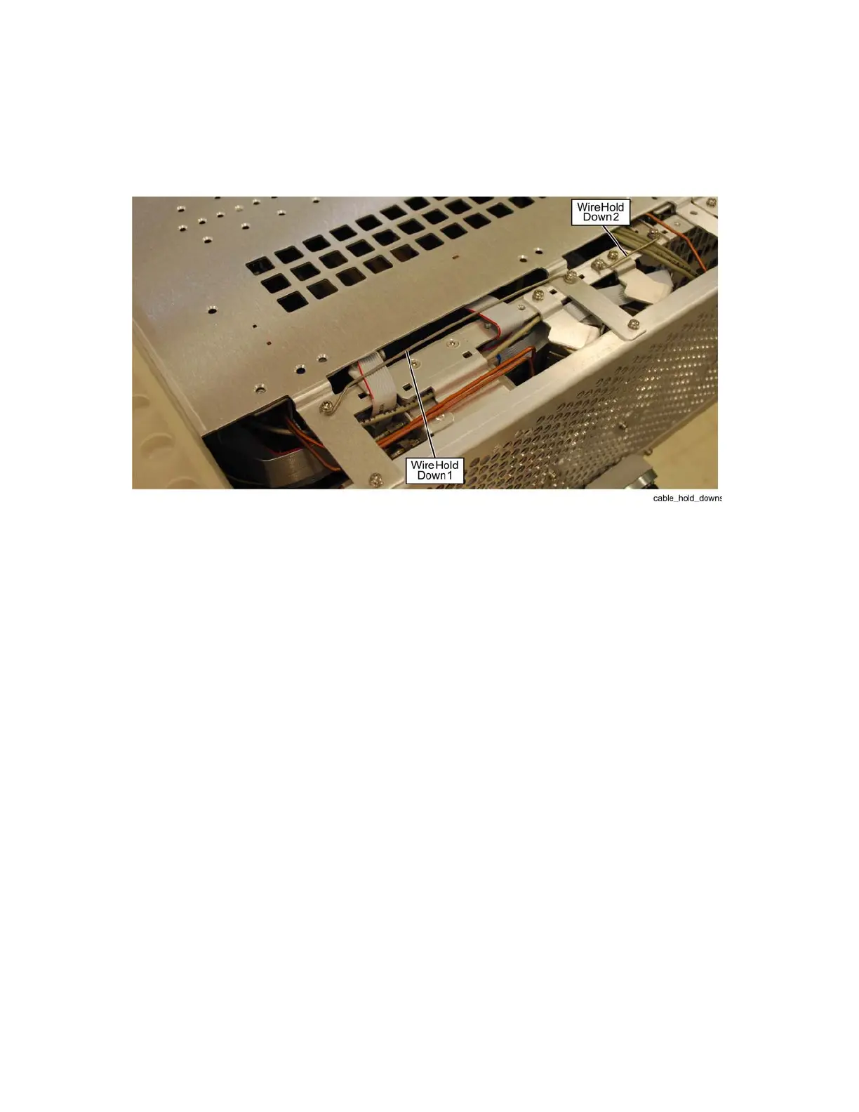
6. Refer to Figure 16-71. Remove the other screw (0515-0372) attaching the
reference wire hold down 2 to the chassis. Remove wire hold down 2.
Figure 16-71 Wire Hold Downs
7. Remove cables W32, W33, W35 (Opt BBA), W36, W37, W39, and W47
from the Reference assembly.
8. The reference assembly can be removed from the chassis by using the
ejectors to pull the board up out of the chassis.
Replacement
1. Slide the reference assembly into slot 2 in the chassis and press down to
plug it into the motherboard using the ejectors to push into place.
2. Refer to Figure 16-71. Reinstall the two screws (0515-0372) to attach wire
hold down 2 to the chassis and the screw on the other side attaching the
Reference board to the chassis. Torque to 9 inch-pounds.
3. Refer to Figure 16-70. Replace cables W3, W18, W31, W32, W33, W35
(Opt BBA), W36, W37, W39, and W47 to the correct locations. Torque the
semi-rigid cables to 10 inch-pounds.
4. Replace the top brace. Refer to the Top Brace and Power Supply Bracket
replacement procedure.
5. Replace the instrument outer case. Refer to the Instrument Outer Case
replacement procedure.