N9030B PXA Signal Analyzer Service Guide 539
Assembly Replacement Procedures
Front Frame Assembly
Front Frame Assembly
Removal
1. Remove the instrument outer case. Refer to the Instrument Outer Case
removal procedure.
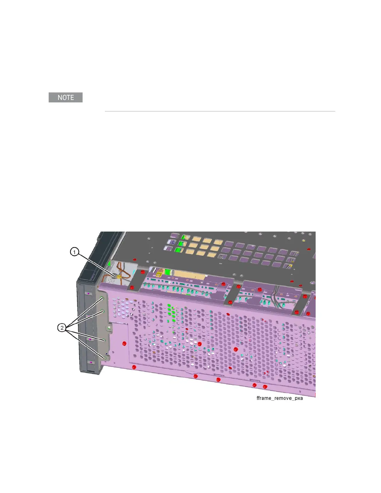
2. If Option EXM, External Mixing, is installed disconnect semi-rigid cable
connection (1) on LO/IF cable.
3. Refer to Figure 16-98. Using the T-10 driver, remove the eight screws (2)
(0515-2032), four on each side, to detach the Front Frame Assembly from
the chassis.
4. Refer to Figure 16-99. Pull the Front Frame Assembly carefully away from
the chassis. Remove the ribbon cable W1 from the motherboard. The
cable has locking tabs on each side, pinch and pull to release.
Figure 16-98 Front Frame Assembly Removal
Make sure any connectors on the front panel are removed.