N9030B PXA Signal Analyzer Service Guide 499
Assembly Replacement Procedures
Front End Control Assembly
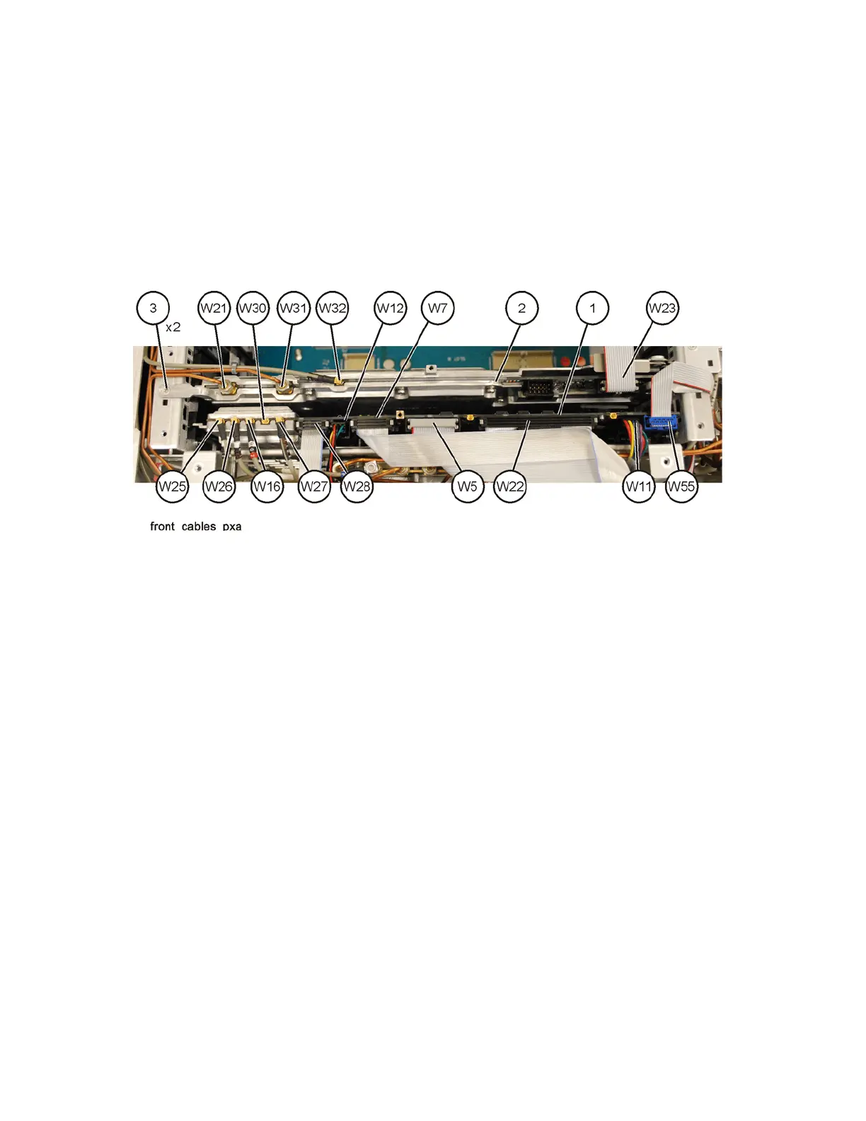
4. Refer to Figure 16-66. Remove the cables W25, W26, W16, W27, and W30
(Opt EXM) from the Front End Control assembly (1).
5. Remove the ribbon cables W5, W22, W28, W7, and W55 and the wire
harnesses W11 and W12 from the Front End Control assembly.
6. The Front End Control assembly can now be unplugged from the
motherboard and lifted out of the chassis.
Figure 16-66 Front End Control Cables
Replacement
1. Refer to Figure 16-66. Install the Front End Control assembly into slot 11
in the chassis and press down to plug it into the motherboard.
2. Reattach the ribbon cables W5, W22, W28, W7, and W55 and the wire
harnesses W11 and W12 to the Front End Control assembly.
3. Reattach the cables W25, W26, W16, W27, and W30 (Opt EXM) to the
Front End Control assembly.
4. Replace the instrument top brace. Refer to the Top Brace and Power
Supply Bracket replacement procedure.
5. Replace the instrument outer case. Refer to the Instrument Outer Case
replacement procedure.