246 N9030B PXA Signal Analyzer Service Guide
Analog/Digital IF Troubleshooting
A3 Digital IF Troubleshooting
Verifying the 100 MHz Reference Input
1. Perform an instrument shutdown.
2. Remove the cover of the PXA Signal Analyzer. Refer to Chapter 16,
“Assembly Replacement Procedures”, on page 429 in this service guide.
3. Turn the instrument over so that the bottom side of the analyzer is facing
up.
4. Turn on the PXA Signal Analyzer and wait for the instrument to complete
the boot up process.
5. Press System, Alignments, Auto Align, Off.
6. Press Input/Output, RF calibrator, 50 MHz.
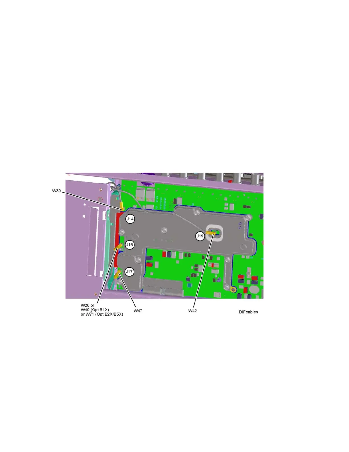
7. Referring to Figure 7-11, carefully disconnect W39 cable at A3J14.
Figure 7-11 A3 Digital IF Cables
8. Connect the W39 cable to the MMCX female to SMA female connector.
Use an appropriate cable to go from the SMA connector to the RF input of
a functioning spectrum analyzer to verify the 100 MHz reference frequency
and amplitude is correct.
9. Press AMPTD, Ref Level, 20 dBm, Freq, 100 MHz, Span, 1 MHz, Peak
Search on the functioning spectrum analyzer.