EasyManuals Logo

Keysight Technologies N9030B User Manual

Keysight Technologies N9030B
617 pages
To Next Page IconTo Next Page
To Previous Page IconTo Previous Page
Page #473 background imageLoading...
Page #473 background image
N9030B PXA Signal Analyzer Service Guide 473
Assembly Replacement Procedures
RF Area (Options 544, 550)
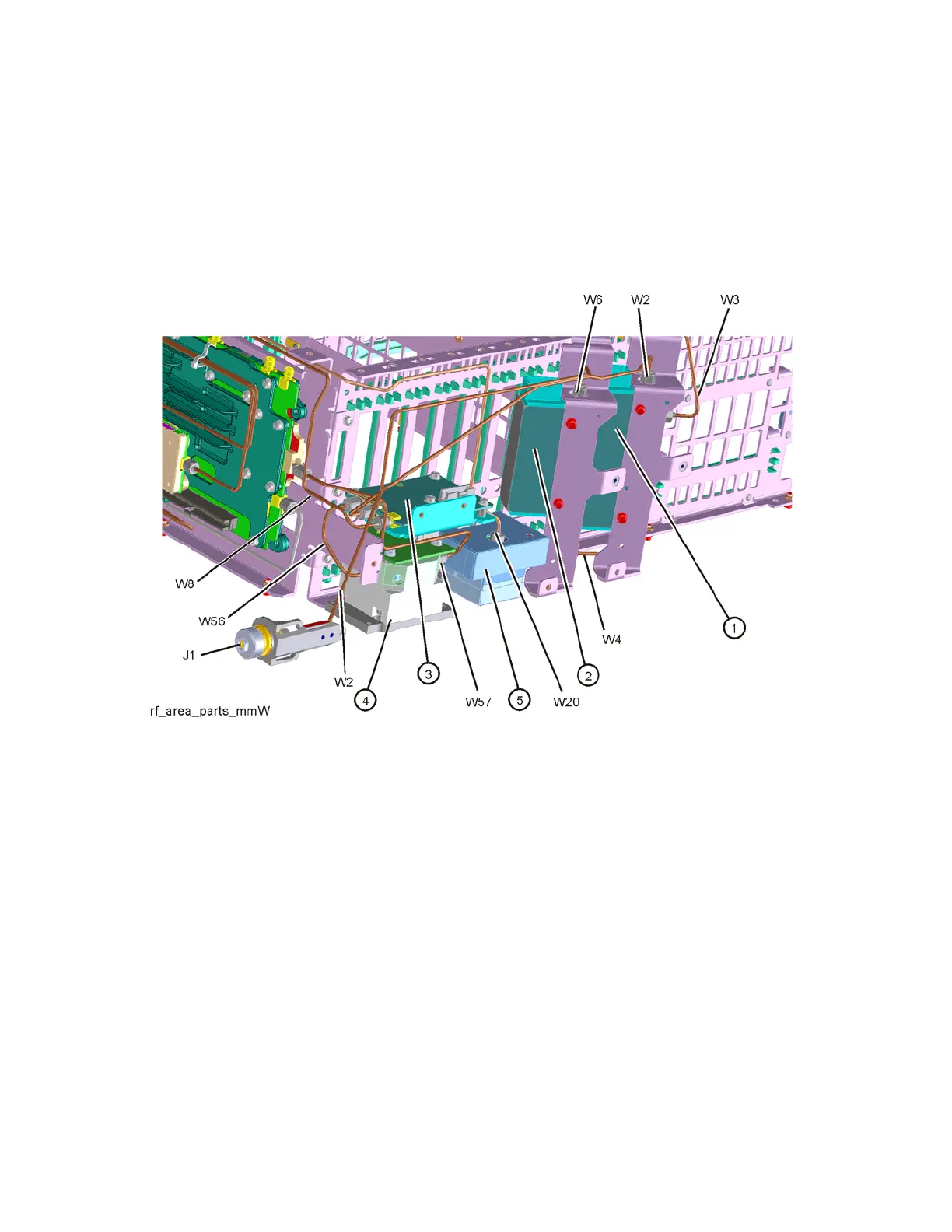
Refer to Figure 16-42. The RF area consists of RF attenuator A (1), RF
attenuator B (2), low band switch assembly (3), YTF Preselector (4), and YTO
(5).
Figure 16-42 RF Area Components and Cables
(Options 544, 550)
To gain access to the attenuators, low band switch, YTF Preselector, YTO,
Option MPB, or Option LNP for removal, follow these steps:
1. Remove the instrument outer case. Refer to the Instrument Outer Case
removal procedure.
2. Remove the front panel. Refer to the Front Frame Assembly removal
procedure.

Table of Contents

Other manuals for Keysight Technologies N9030B

Questions and Answers:

Question and Answer IconNeed help?

Do you have a question about the Keysight Technologies N9030B and is the answer not in the manual?

Keysight Technologies N9030B Specifications

General IconGeneral
BrandKeysight Technologies
ModelN9030B
CategoryMeasuring Instruments
LanguageEnglish

Related product manuals