472 N9030B PXA Signal Analyzer Service Guide
Assembly Replacement Procedures
RF Area (Options 503, 508, 513, 526)
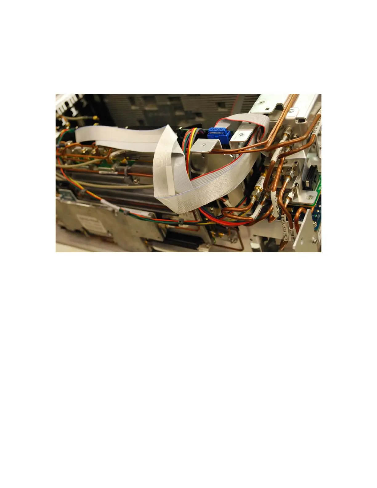
18.Refer to Figure 16-41. Route all ribbon cables as shown to avoid being
damaged when the top brace is installed.
Figure 16-41 Ribbon Cable Routing
19.Refer to Figure 16-7. Position the RF bracket onto the chassis and replace
the sixteen screws (0515-0372). Torque to 9 inch-pounds.
20.Replace the front panel. Refer to the Front Frame Assembly replacement
procedure.
21.Replace the instrument outer case. Refer to the Instrument Outer Case
replacement procedure.