268 N9030B PXA Signal Analyzer Service Guide
LO Synthesizer/Reference Troubleshooting
A16 Reference Assembly Troubleshooting
A16 Reference Assembly Troubleshooting
If the A16 Reference Assembly is suspect, verify the reference signals, local
oscillator output frequencies, and power levels as per Table 8-4 using a
functioning spectrum analyzer. In order to measure the signals, you will need
to remove the top brace. Refer to the “Top Brace and Power Supply Bracket”
removal procedure on page 436 for details.
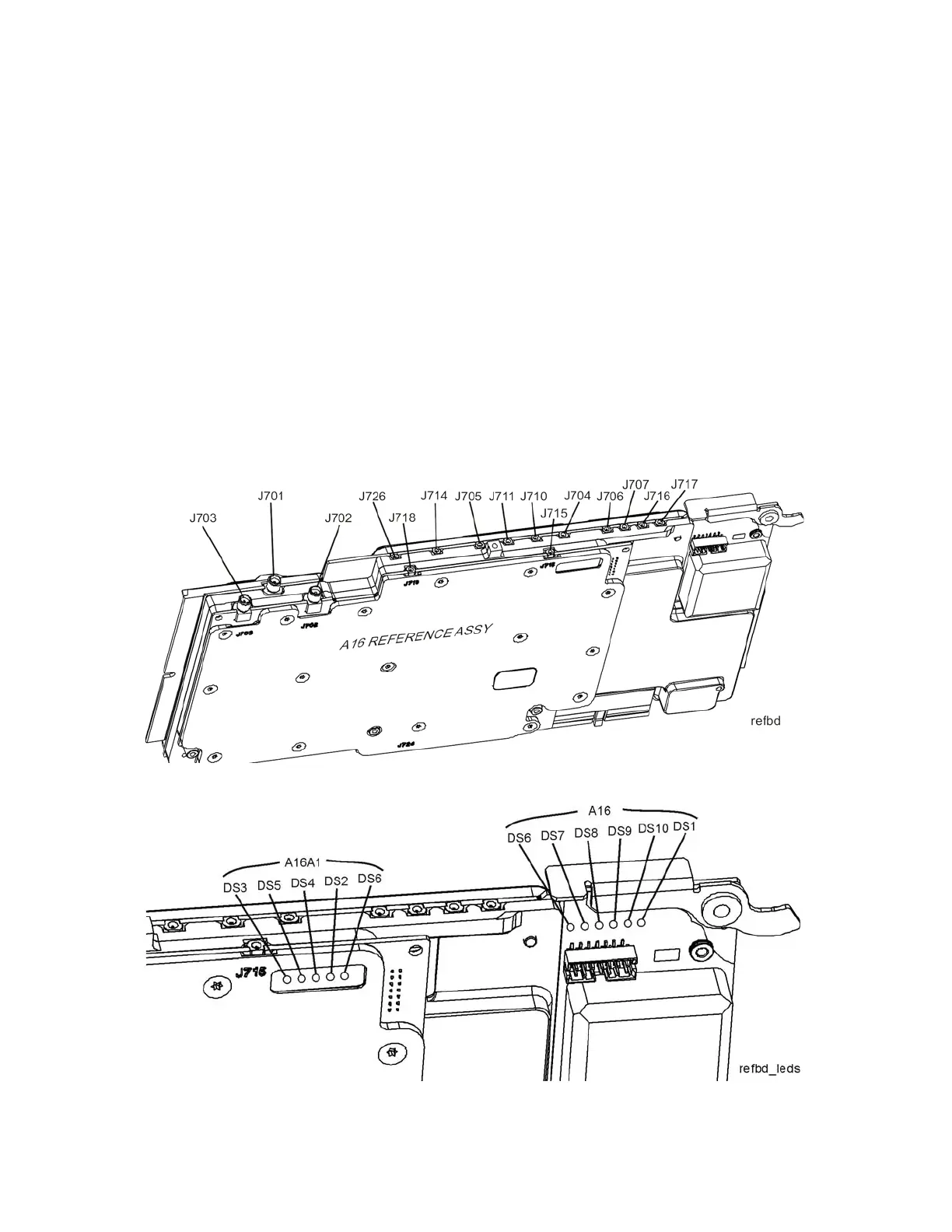
The board layout in Figure 8-13 and Figure 8-14 below identifies the input and
output connectors and LEDs on the A16 Reference Assembly.
If the outputs measure correctly, the A16 Reference Assembly is functioning
correctly. If not, the Reference Assembly is the most probable cause provided
the power supply is operating correctly. Refer to “A7 Midplane Board
Assembly Troubleshooting” on page 310 if the power supplies are suspect.
Table 8-4 A16 Reference Assembly Signal Measurement Details
Figure 8-13 A16 Reference Assembly
Figure 8-14 A16 Reference LEDs