N9030B PXA Signal Analyzer Service Guide 475
Assembly Replacement Procedures
RF Area (Options 544, 550)
Attenuators
Removal
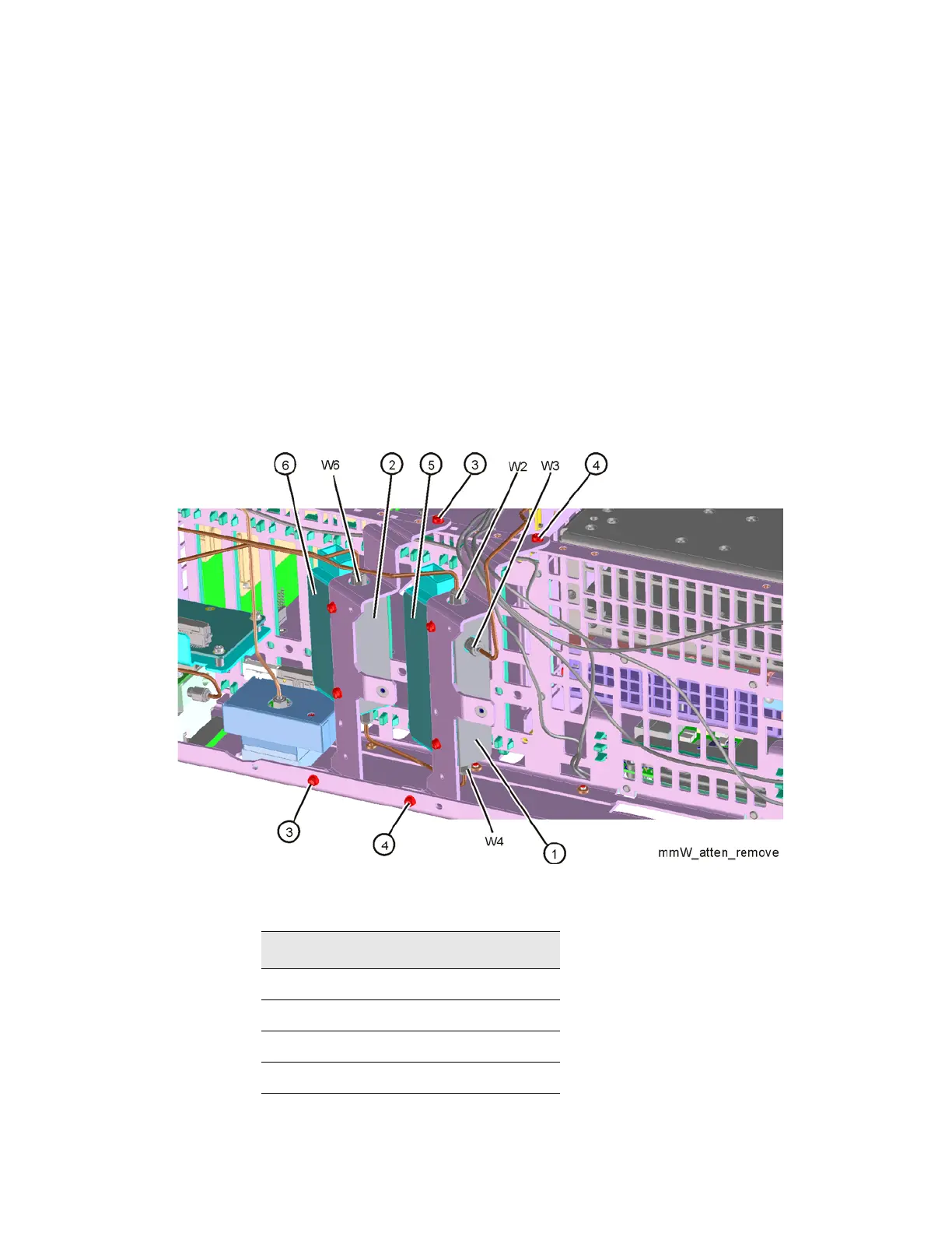
1. Refer to Figure 16-44. To remove Attenuator A (1) or Attenuator B (2),
remove the semi-rigid cables W2, W3, W4, or W6 attached to the
attenuator using the 5/16 inch wrench.
2. Remove the ribbon cable attached to the attenuator.
3. Remove the two screws (3) or (4) (0515-0372) for each attenuator
bracket to remove from the chassis using the T-10 driver.
4. Remove the attenuator and magnetic shield (5) or (6) from the bracket
by removing the two screws (0515-0372).
Figure 16-44 Attenuators Removal
Table 16-11
Item Keysight Part Number
W2 N9020-20173
W3 N9020-20072
W4 N9020-20068
W6 N9010-20004