N9030B PXA Signal Analyzer Service Guide 527
Assembly Replacement Procedures
Wideband Extension Board (Option RTS)
Replacement
1. Refer to Figure 16-87. Place the W28 Wideband Extension board into the
chassis in the position shown. Route the flex circuit cables behind the
attenuators. Attach the board to the chassis with the four screws (1).
Torque to 9 inch-pounds.
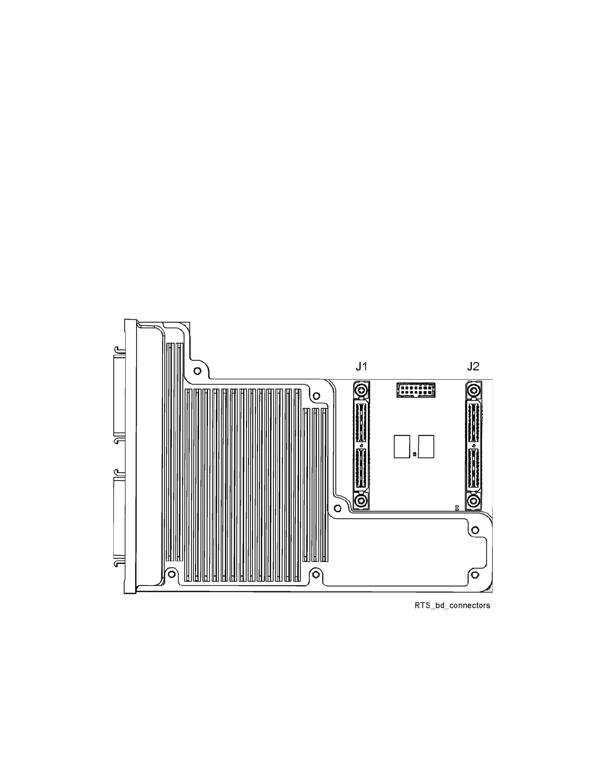
2. Refer to Figure 16-89. Connect the flex circuit cables to the Wideband
Digital boards in the card cage. If the instrument has only one WB DIF
board, connect the flex circuit cable from the Wideband Extension J1 to
the connector on the WB Digital IF assembly.
If the instrument has two WB Digital IF boards, connect the flex circuit
attached to the Wideband Extension J2 (J2 is connector is on the edge of
the Wideband Extension) to the front WB Digital IF board in the card cage.
Connect the other flex circuit from the WB Digital IF Extension J1 to the
rear WB Digital IF board in the card cage.
Figure 16-89 Wideband Extension Board Connectors
3. Replace the RF panel as described on page page 439.
4. Replace the top brace. Refer to the “Top Brace and Power Supply Bracket”
replacement procedure.
5. Replace the instrument outer case. Refer to the “Instrument Outer Case”
replace procedure.