526 N9030B PXA Signal Analyzer Service Guide
Assembly Replacement Procedures
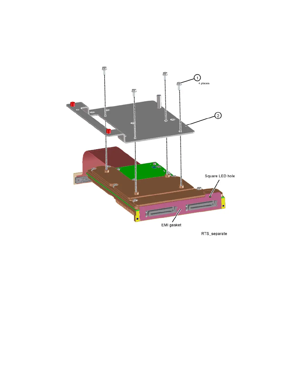
Wideband Extension Board (Option RTS)
4. Refer to Figure 16-88. To separate the bracket (2) from the Wideband
Extension board, remove the four screws (1) (0515-0372).
Figure 16-88 Wideband Extension Board and Bracket Separation
5. Attach the bracket to the new Wideband Extension board with the four
screws. Torque to 9 inch-pounds.
6. Remove the flex circuit cable(s) from the old board and attach to the new
Wideband Extension board, taking care to connect them to the same
connectors as the old board. Refer to Figure 16-89. Option B2X
instruments will have one flex cable. Option B5X instruments will have two
flex cables.
7. When replacing the EMI gasket, notice the gasket has a small square hole
and needs to be aligned with the square hole on the Wideband Extension
Board casting. There is an LED in the casting, and the small square hole
allows the LED to be visible from the rear panel.
The gasket is fragile. Carefully peel off the backing from the gasket and
apply the sticky side of the gasket over the two Wideband Extension board
connectors.