506 N9030B PXA Signal Analyzer Service Guide
Assembly Replacement Procedures
Option B1X
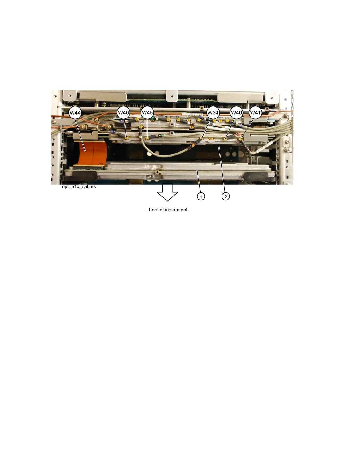
4. Refer to Figure 16-73. Remove cables W34, W40, W41, W45, and W46
from the Wideband Analog IF assembly (2 ).
5. Remove ribbon cables W44.
Figure 16-73 Option B1X Cables
6. The Wideband Analog IF (2) and Wideband Digital IF (1) assemblies can
now be removed by pulling up on the ejectors to remove from the chassis.
Replacement
1. Slide the Wideband Analog IF assembly into slot 3 in the chassis and use
the ejectors to push into place into the motherboard.
2. Slide the Wideband Digital IF assembly into slot 5 in the chassis and use
the ejectors to push into place into the motherboard.
3. Refer to Figure 16-73. Reinstall cables W34, W40, W41, W45, and W46 to
the Wideband Analog IF assembly (2).
4. Reconnect ribbon cable W44.
5. Replace the top brace. Refer to the Top Brace and Power Supply Bracket
replacement procedure.
6. Replace the instrument outer case. Refer to the Instrument Outer Case
replacement procedure.