N9030B PXA Signal Analyzer Service Guide 501
Assembly Replacement Procedures
LO Synthesizer Assembly
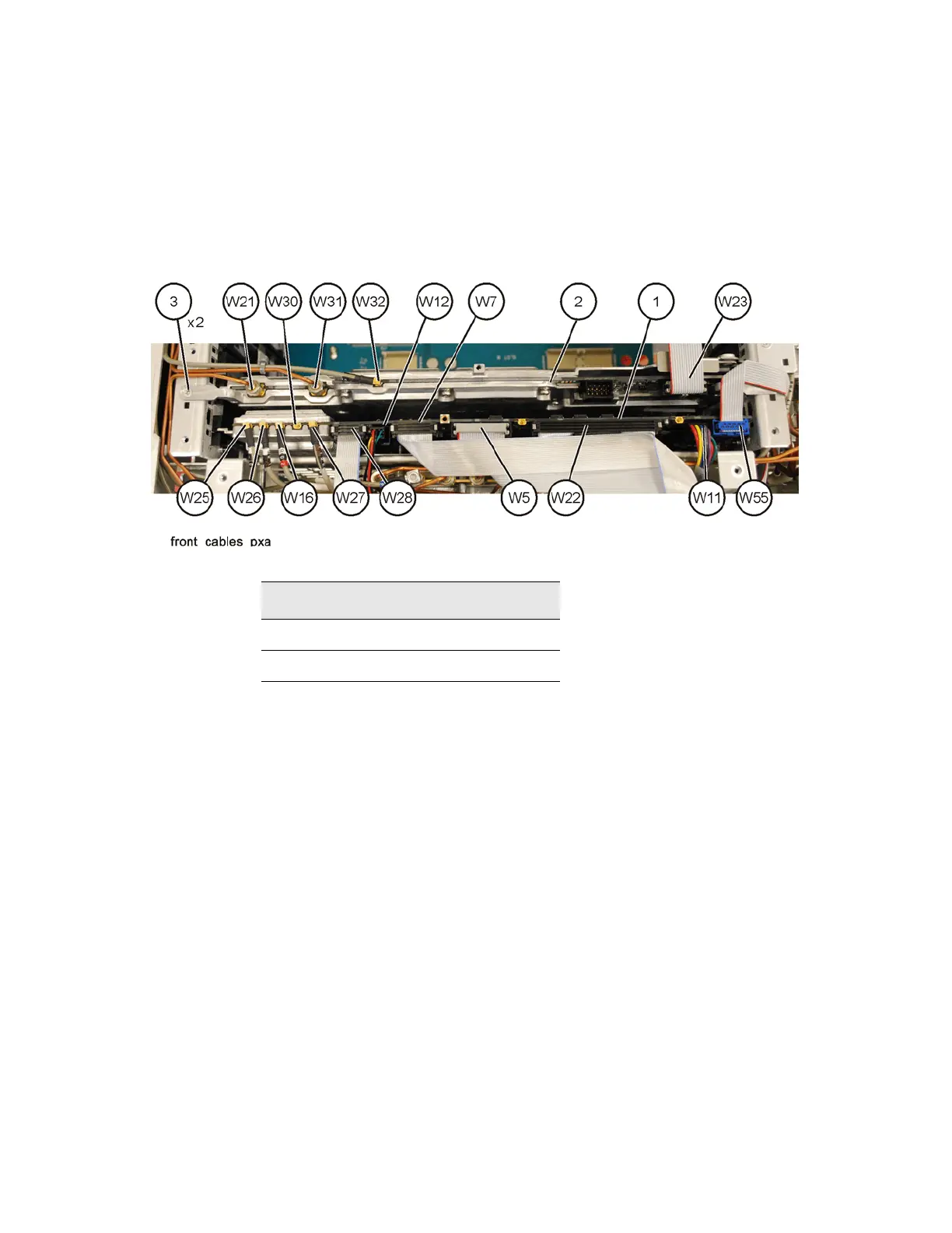
4. Refer to Figure 16-68. Remove the cables W21 and W31 from the LO
Synthesizer assembly (2) using the 5/16 inch wrench.
5. Remove W23 and W32.
6. Remove the two screws (3) (0515-2032).
Figure 16-68 LO Synthesizer Assembly Removal
7. Use the ejectors on the LO Synthesizer assembly to unplug from the
motherboard and lift out of the chassis.
Replacement
1. Refer to Figure 16-68. Install the LO Synthesizer assembly into slot 10 in
the chassis securing with the ejectors.
2. Reattach the cables W21 and W31 to the LO Synthesizer assembly.
Torque to 10 inch-pounds.
3. Reattach the cables W23 and W32.
4. Reinstall the two screws (3) (
0515-2032). Torque to 9 inch-pounds.
5. Replace the instrument top brace. Refer to the Top Brace and Power
Supply Bracket replacement procedure.
6. Replace the instrument outer case. Refer to the Instrument Outer Case
replacement procedure.
Table 16-15
Item Keysight Part Number
W21 N9020-20019
W31 N9020-20021