90 Keysight EXG and MXG X-Series Signal Generators User’s Guide
Optimizing Performance for All Models
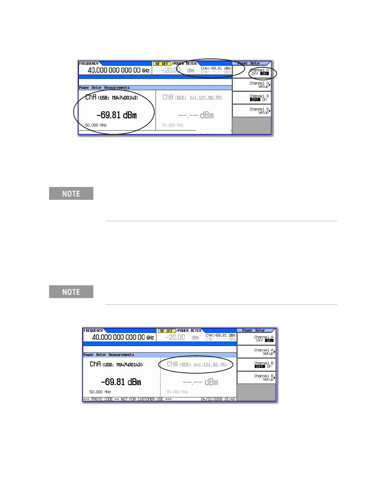
Using the Dual Power Meter Display (with USB U2000A Series Power Sensors)
Figure 5-8 Channel A Power Sensor Displayed on MXG/EXG
6. On the N1912A P–Series Power Meter (Channel B power sensor): Connect the N1912A P–
Series Power Meter to the LAN.
7. Connect the power meter sensor to channel B of the power meter.
8. Connect the power sensor input to the 50 MHz reference of the power meter.
9. Press Channel B Setup
10.Press Connection Settings > Sockets
11.Press IP Address > IP address > Enter
Figure 5-9 Channel B Power Sensor with IP Address Entered
12.Press Return > Channel Settings > External Power Meter Channel to B.
It is recommended, but not required to use the channel B on the N1912A.
This provides continuity with the signal generator’s dual display. For this
example, the U2004A has already used up the channel A position on the
signal generator.
The IP address of the power meter should be displayed in the ChB section
of the display.
For details on
each key, use key
help as described
on page56.
For details on
each key, use key
help as described
on page56.