Keysight B2980B User’s Guide, Edition 1 107
How to Perform Measurement
Resistance Measurement
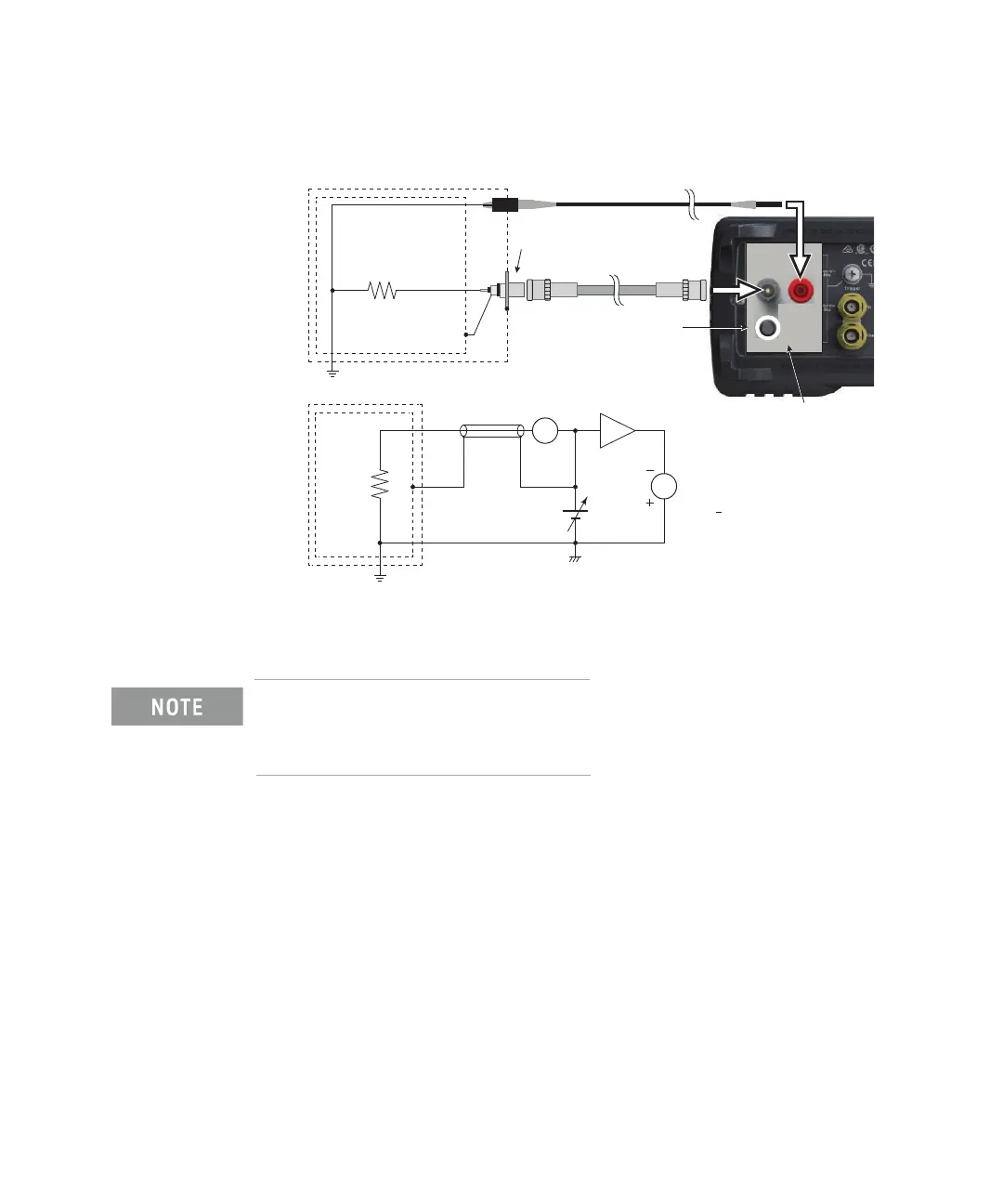
Figure 3-15 Grounded Device Measurement using N1414A
For the grounded device measurement, set the N1414A control switch to the
PUSH position. Also set the voltage source Low terminal state to FLOATING.
The connection shown in Figure 3-15 applies the voltage to the Common terminal
from the Voltage Source. The voltage up to 500 V can be applied to the Common
terminal.
Procedure You can perform the resistance measurement as follows.
Step 1. Set the resistance calculation mode, Vs/Im or Vm/Im. See “Resistance
Calculation Mode” on page 109.
Step 2. Press the View key and select the Meter View function key to display the Meter
view.
Step 3. Press the OHMS (R) assist key to set the resistance measurement mode.
Step 4. Set the current measurement range and the output voltage. See “V Control
Mode” on page 109.
Input
Triaxial cable
Triaxial bulkhead connector
N1414A adapter
High voltage test lead
Low
Common is connected to Voltage Source High
through the N1414A adapter.
Guard shield
Control switch:
PUSH position
Shield
RX
Input
RX
Low
Guard
shield
Shield
A
V
Common
VS
VM = 0.01*VS
VM
Voltage Source Low Terminal State:
FLOATING
100:1
 Loading...


