configuration is for loads that require a large amount of
starting torque, such as elevators or lifts.
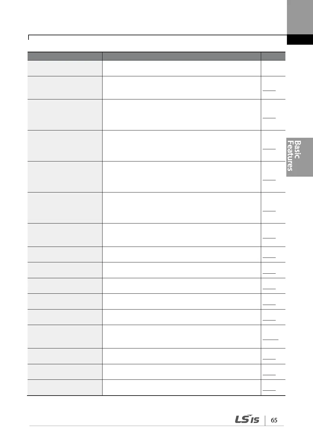
Output voltage adjustment
Adjusts the output voltage to the motor when the power
supply to the inverter differs from the motor’s rated input
p.102
Accelerating start
Accelerating start is the general way to start motor operation.
The typical application configures the motor to accelerate to a
target frequency in response to a run command, however
there may be other start or acceleration conditions defined.
p.103
Start after DC braking
Configures the inverter to perform DC braking before the
motor starts rotating again. This configuration is used when
the motor will be rotating before the voltage is supplied from
p.103
Deceleration stop
Deceleration stop is the typical method used to stop a motor.
The motor decelerates to 0 Hz and stops on a stop command,
however there may be other stop or deceleration conditions
p.104
Stopping by DC braking
Configures the inverter to apply DC braking during motor
deceleration. The frequency at which DC braking occurs must
be defined and during deceleration, when the motor reaches
the defined frequency, DC braking is applied.
p.105
Free-run stop
Configures the inverter to stop output to the motor using a
stop command. The motor will free-run until it slows down and
p.106
Power braking
Configures the inverter to provide optimal, motor deceleration,
without tripping over-voltage protection.
p.107
Start/maximum frequency
configuration
Configures the frequency reference limits by defining a start
frequency and a maximum frequency.
p.108
Upper/lower frequency limit
configuration
Configures the frequency reference limits by defining an upper
limit and a lower limit.
p.108
Frequency jump
Configures the inverter to avoid running a motor in
mechanically resonating frequencies.
p.110
2
nd
Operation Configuration
Used to configure the 2
nd
operation mode and switch between
the operation modes according to your requirements.
p.111
terminal control
Enables the user to improve the responsiveness of the multi-
function input terminals.
p.112
P2P communication
configuration
Configures the inverter to share input and output devices with
other inverters.
p.113
Multi-keypad configuration
Enables the user to monitor multiple inverters with one
monitoring device.
p.114
User sequence configuration
Enables the user to implement simple sequences using various
function blocks.
p.115