777 SERVICE MANUAL HYDRAULIC SYSTEM
Manitowoc Published 10-01-2012, Control # 045-08 2-23
2
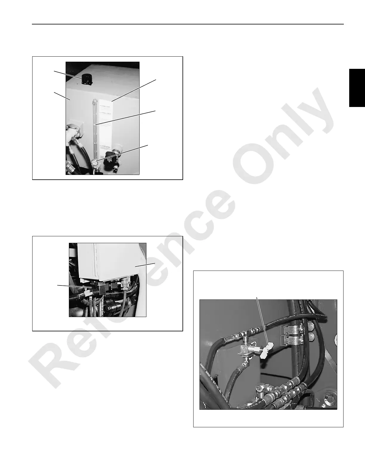
8. Fill hydraulic tank to FULL HOT level mark on sight
gauge (Figure 2-23).
9. As tank is filled, monitor bleed port at Filter 1
(Figure 2-22). Oil will flow by gravity from hydraulic tank
to filter.
Securely install cap on bleed port when clear oil flows.
10. Disconnect fuel solenoid electrical plug (Figure 2-24) to
keep engine from starting while filling Filters 3, 4, and 6.
11. Crank engine for 10 seconds or until clear oil flows from
bleed port at Filters 3, 4, and 6 (Figure 2-22). If oil does
not appear, crank engine for 10 more seconds.
Securely install cap on bleed ports when clear oil flows.
12. Reconnect fuel solenoid electrical plug (Figure 2-24).
Pressure Sender Calibration
Perform this procedure before Initial Start-Up.
The following procedure only applies when the crane does
not a boom. When the crane has a boom, use the
procedure contained in Pressure Sender Calibration in
this section.
1. Stop engine.
2. Perform following steps for boom hoist cylinder pressure
sender before proceeding:
a. Securely close shut-off valve for boom hoist cylinder
pressure sender (Figure 2-25) — turn
CLOCKWISE.
b. Connect a bleed line with a shut-off valve to coupler
for boom hoist cylinder pressure sender (item 5,
Figure 2-27).
c. Open valve in bleed line to bleed oil. Use a suitable
container to catch oil flow.
3. Turn ON cab power switch.
4. Turn crane mode selector key counterclockwise to
CONFIRM position and hold.
5. Press engine run/stop switch to RUN position.
6. Continue to hold crane mode selector key in CONFIRM
position for ONE MINUTE after performing step 5.
7. Check for proper calibration — with engine off (key in
RUN), charge pressure on diagnostic screen for each
crane function should be 50 psi (3.4 bar) or less.
8. Remove bleed line from coupler for boom hoist cylinder
pressure sender.
9. Fully open shut-off valve for boom hoist cylinder
pressure sender (Figure 2-25). Erratic boom hoist
operation will occur if this step is not performed.
P454
Hydraulic
Tan k
Fill Cap
Level
Decal
Sight
Gauge
Temperature
Gauge
FIGURE 2-23
P438
Junction
Box
Fuel
Solenoid
Electrical
Plug
Right Side of Engine
FIGURE 2-24
FIGURE 2-25
Shut-Off Valve
for Boom Hoist Cylinder
Pressure Sender
Turn CLOCKWISE to CLOSE
Between Rear Drum
and Hydraulic Tank
P985

 Loading...


