ELECTRIC SYSTEM 777 SERVICE MANUAL
3-2 Published 10-01-2012, Control # 045-08
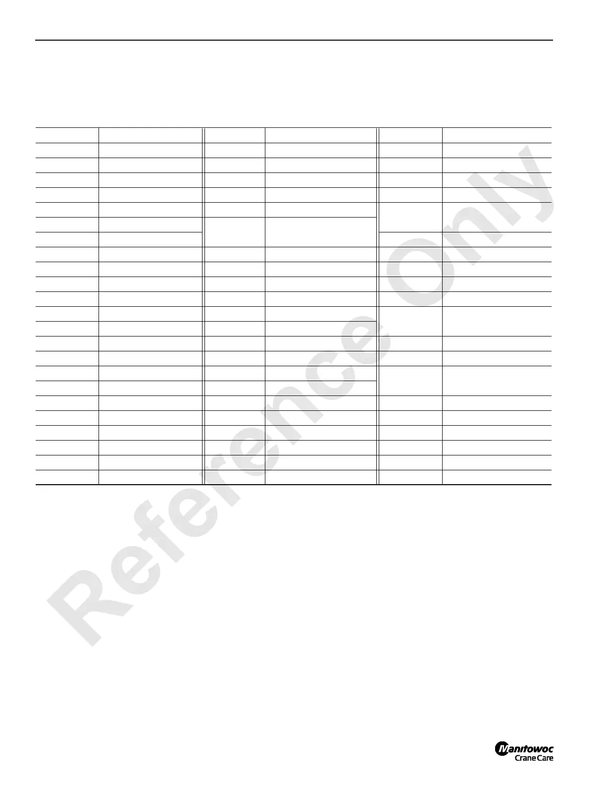
ABBREVIATIONS AND SYMBOLS
See Table 3-2 for abbreviation and symbols used in this
section.
Table 3-2 Abbreviations and Symbols
ITEM DEFINITION ITEM DEFINITION ITEM DEFINITION
+/- Plus/Minus Value D1 Digital - On/Off Inputs N/C Normally Closed (Switch)
+ Plus/Positive Volts D2 Digital Inputs Nm Newton Meters
- Minus/Negative Volts D3 Digital Inputs or Outputs N/O Normally Open (Switch)
% Percent DI Digital Inputs No. Number
° or DEG Degrees - Angular DO Digital Outputs
OEM
Original Equipment
Manufacturer
°F or DEG F Degrees - Temperature
EDC
Electrical Displacement
Control
PC Programmable Computer
A (amp) Ampere FFall Free Fall PCP Pressure Controller Pilot
A1 Handle Inputs Ft. lbs Foot Pounds Pot Potentiometer
A2 Pump Control Outputs GND Ground PSI/PRESS Pounds Per Square Inch
A3 Programmer’s Screen GPM Gallons Per Minute PSIA PSI Absolute
AC Alternating Current HYD Hydraulic
RCL
Rated Capacity
Indicator/Limiter
ACC Accessory System I/O Input/Output
ANG Angle INFALL Intermediate Fall Reg. Regulated
Aux. Auxiliary LED Light Emitting Diode RPM Revolution Per Minute
BHST Boom Hoist L/m Liters Per Minute
SAE
Society of Automotive
Engineers
CAL or CALIB Calibration Luff Luffing
CHA or CHB Channel A or B mA Mega Amps TB Terminal Block
COMM Communication MAX Maximum TEMP Temperature
CON Configuration MIN Minimum TRK Track (Crawler
CPU Central Processing Unit MM Millimeter V Volts
CYL Cylinder MPH Mile Per Hour VAC Volts Alternating Current
DC Direct Current NC No Connection VDC Volts Direct Current

 Loading...


