INTRODUCTION 777 SERVICE MANUAL
1-20 Published 10-01-2012, Control # 045-08
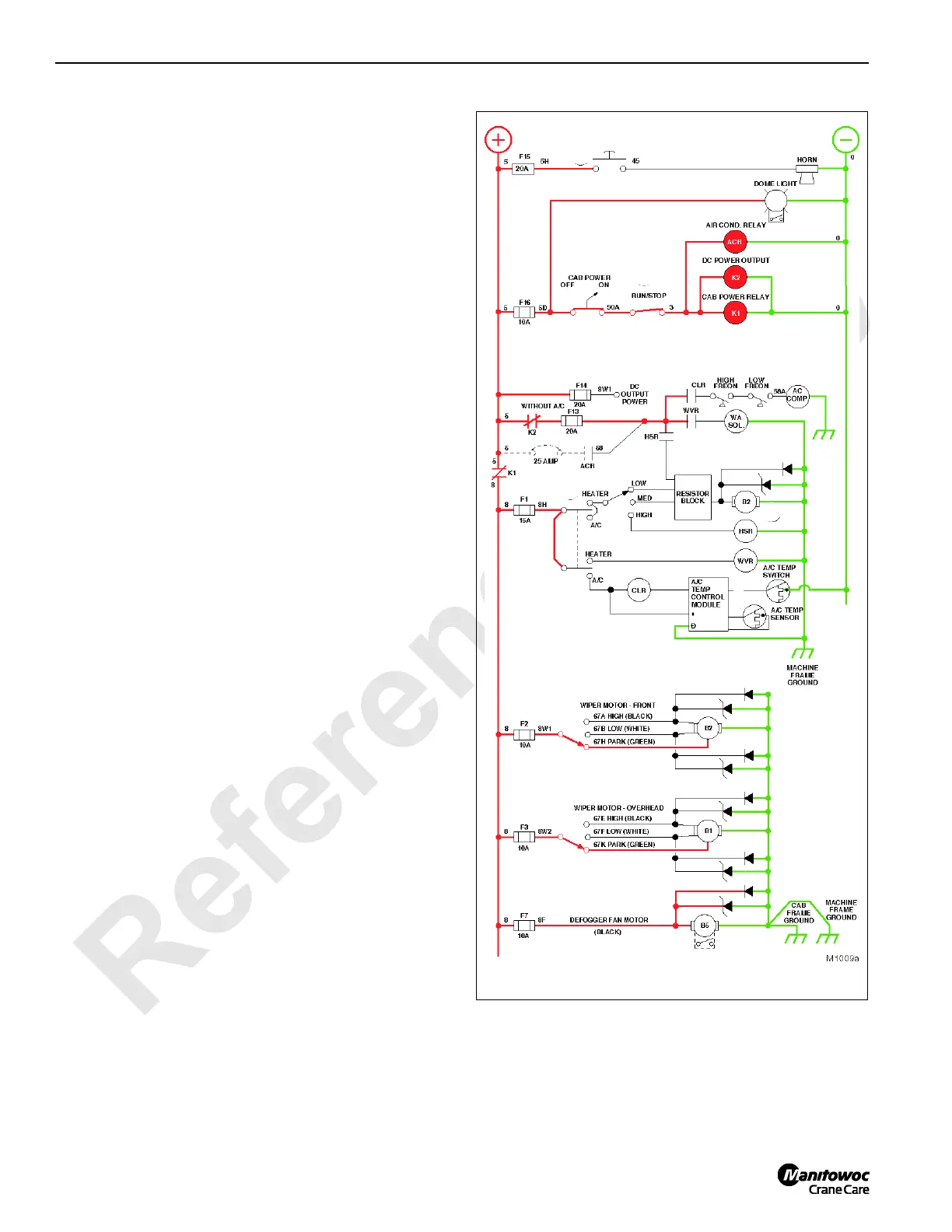
Voltage Availability
See Figures 1-12, 1-13, 1-14 and 1-15 for following
procedures.
Accessory Circuits
Voltage is available at key-operated cab power on/off switch,
dome light switch, and horn switch. After cab power switch is
activated, voltage is available to the run/stop, which when
activated, provides power to cab power relay Kl, DC power
output relay K2, and Air Conditioner Relay ACR.
When the contacts of Kl close, voltage is available to the
accessory controls including front and overhead wiper motor
three-speed position switches, and defogger motor switch.
Power is also available to the heater/AC switch when
activated, provides power for AC or heater function
depending upon mode selected. When heater function is
selected, water valve relay WVR energizes and closes the
contacts to WA solenoid permitting engine water to flow
through the heater core. When AC function is selected and
when the climatic temperature control switch is in the closed
position, the clutch relay CLR energizes causing the contacts
to close and the AC clutch to engage. The fan motor used
with either the heater or AC system, is also activated when
the heater/AC switch selects the desired mode. Fan motor
three-speed selector switch provides low and medium
speeds that are directly controlled by inline resistance and
high speed. When fan motor is selected, high speed relay
HSR closing contacts, HSR providing full current at higher
amperage level to the fan motor.
FIGURE 1-12

 Loading...


