POWER TRAIN 777 SERVICE MANUAL
7-6 Published 10-01-2012, Control # 045-08
ENGINE THROTTLE ADJUSTMENT -
CUMMINS C330
The throttle assembly for the Cummins C330 engine consists
of a hand throttle in the left control console, a foot pedal on
the cab floor, two controllers with potentiometers, EFC
(electronic fuel control) on the engine, associated linkage,
and electrical connections.
In the right control console, a reach rod connects the foot
pedal assembly to the lever on the foot throttle controller. An
electric cable connects the switch controller on the manual
throttle in the left control console to the foot throttle controller.
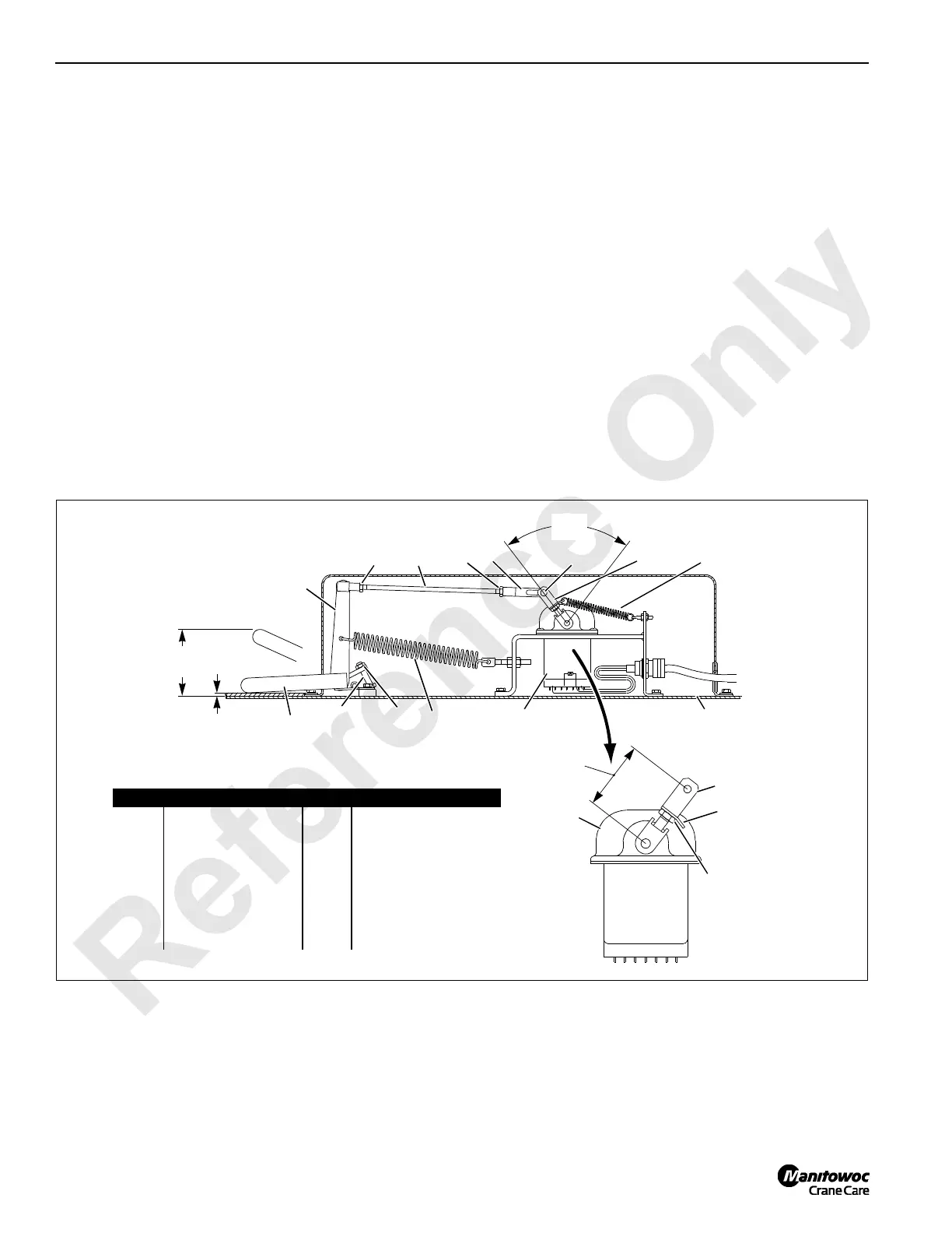
Foot Throttle Linkage Adjustment
See Figure 7-4 for following procedure.
1. Install spring clip (1) and rod end (2) on controller lever
at dimension shown in View A and securely tighten jam
nut (3).
2. Insert a 3/16 in. (5 mm) thick shim or piece of floor mat
between foot pedal and cab floor.
3. Press foot pedal down fully to HIGH IDLE position
against shim or floor mat.
4. Adjust reach rod (4) and rod end (5) so controller lever is
rotated fully to HIGH IDLE position. Securely tighten jam
nuts (6) to lock adjustment.
NOTE: Controllers have internal stops at high and low idle.
5. Release foot pedal to low idle position.
6. Adjust return springs so there is sufficient force to raise
pedal and rotate controller lever to low idle.
7. Adjust pedal stop screw (7). Screw must be tight against
cab floor and there must be 1/8 in. (31 mm) gap between
pin (9) and rear end of slot in rod end (5). Securely
tighten jam nut (8).
8. With foot pedal in LOW IDLE position, distance from top
of pedal to cab floor should be 3-15/16 in. (100 mm).
Electronic Fuel Control Adjustment
See Figure 7-5 for following procedure.
The electronic fuel control (mounted in junction box on
engine) is adjusted at the factory to provide the following
speeds and should not need further attention. Adjustment is
required if the control is replaced. Adjustments are to be
completed in the sequence given in this topic.
The engine clutch must be engaged for all steps. It is
normal for the idle speed to be as high as 1,500 rpm when
the engine clutch is disengaged.
Item Description Item Description
1 Spring Clip 9 Pin
2 Rod End 10 Foot Throttle Controller
3 Jam Nut 11 Foot Pedal
4 Reach Rod 12 Foot Pedal Lever
5 Rod End 13 Spring
6 Jam Nut 14 Cab Floor
7 Pedal Stop Screw 15 Lever
8Jam Nut 16Spring
FIGURE 7-4
Low Idle
High Idle
Low Idle
High Idle
3-15/16 in.
(100 mm)
4566
9
7
8
3/16 in. (5 mm)
Shim or
Floor Mat
75°
Ref.
2
1
3
2-1/4 in.
(57 mm)
View A
A974
10
11
12
13
14
15
16
10

 Loading...


