Manitowoc Published 10-01-2012, Control # 045-08 10-49
777 SERVICE MANUAL TROUBLESHOOTING
10
Test 19 – Testing Hydraulic Solenoid Brake Valves
To determine if a hydraulic solenoid valve is enabled, place
any metallic tool such as a screwdriver on solenoid. Solenoid
is enabled if tool is magnetically pulled toward solenoid.
Testing for voltage at any hydraulic brake valve requires the
use of a standard test plug adapter (which can be ordered
from Manitowoc Cranes, Inc.) and a digital multimeter.
Connect the test plug adapter between the brake valve and
the electrical DIN connector. Make the appropriate
connections (white and black) from the adapter cable to the
digital multimeter and verify 12 volts DC while actuating the
appropriate system function that releases the brake under
test. Load current (amps) can be measured directly by
making the appropriate adapter connections (red and white)
to the digital multimeter.
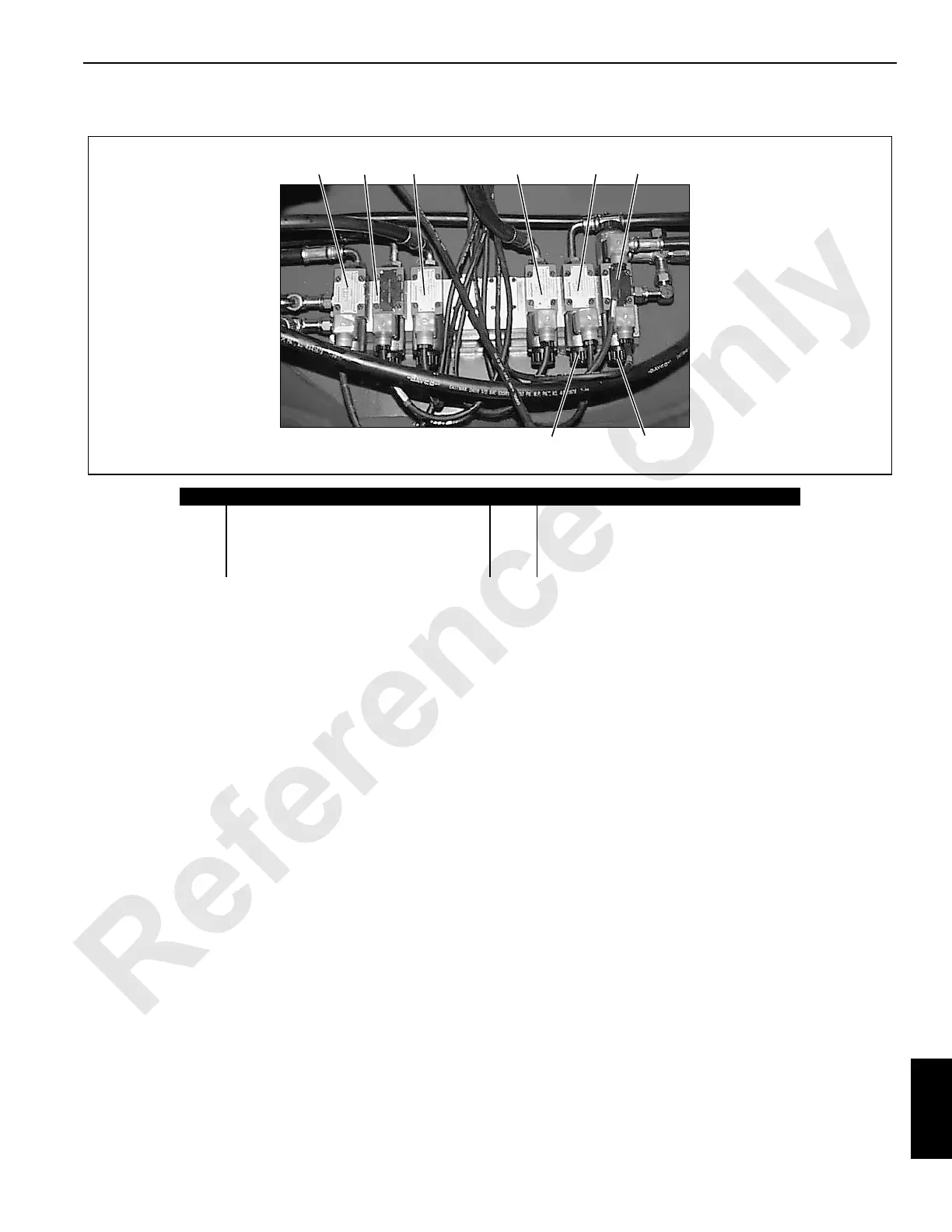
Item Description Item Description
1 Travel 2-speed solenoid valve 5 Swing disc brake solenoid valve
2 Travel disc brake solenoid valve 6 Swing lock in solenoid valve
3 Rear drum disc brake solenoid valve 7 Swing lock out solenoid valve
4 Front drum disc brake solenoid valve 8 Electrical DIN connector
FIGURE 10-24
P515a
1 2 3 54 6
8
7
 Loading...


