ELECTRIC SYSTEM 777 SERVICE MANUAL
3-32 Published 10-01-2012, Control # 045-08
COUNTERWEIGHT LIMIT SWITCH
ADJUSTMENT
NOTE: Do the adjustment in this topic before installing the
counterweights. The counterweight limit switches
are inaccessible once the counterweights are
installed.
The counterweight limit switches prevent over-tensioning the
counterweight handling pendants when installing
counterweights and parking the boom.
If the boom is lowered too far while the handling pendants
are installed, the counterweight tray rises and trips open
either of the two limit switches located under the rear of the
rotating head (Figure 3-12). The computer then stops the
boom down operation, the operating limit alert turns on and
COUNTERWEIGHT MAX UP appears on the digital display.
Adjustment
Bench Setup
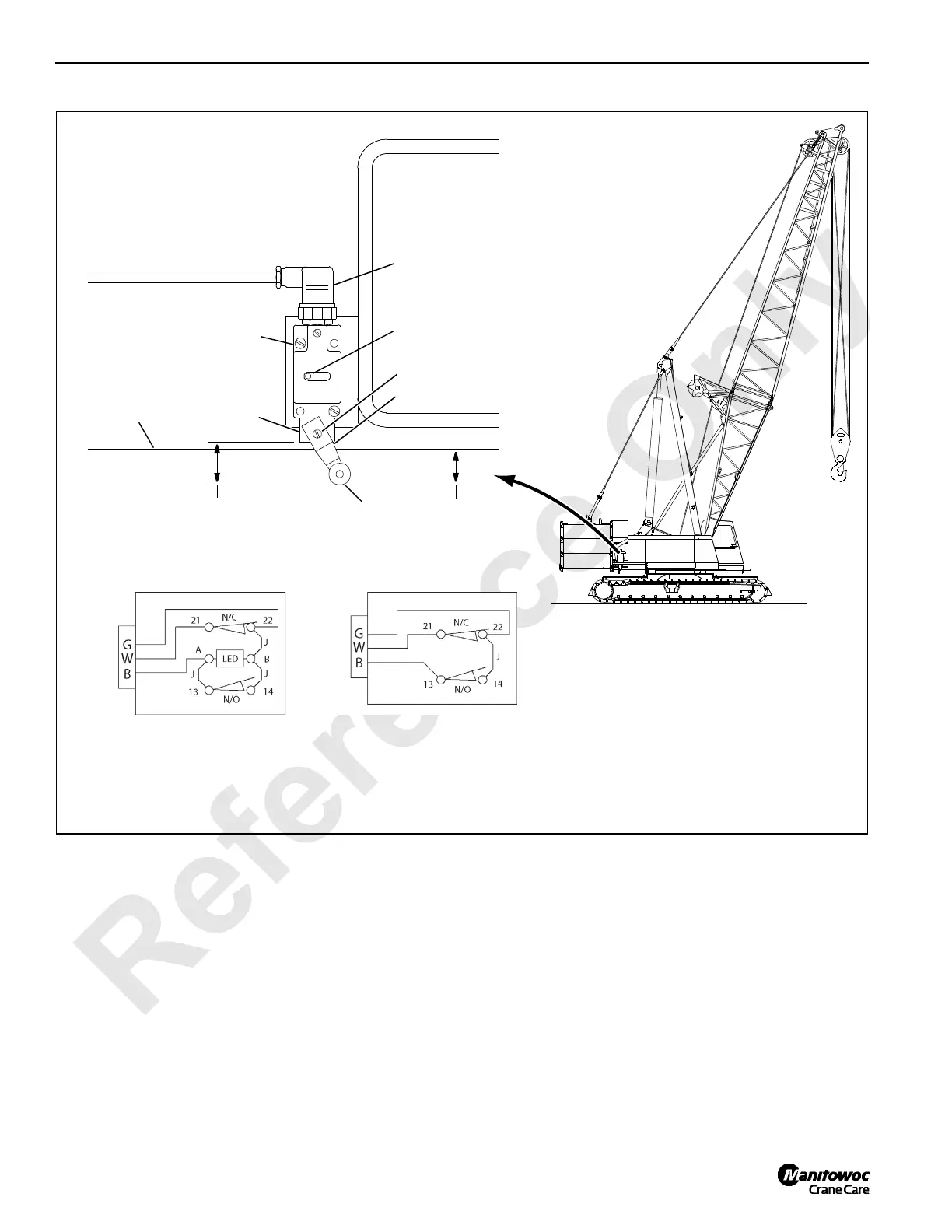
Adjust the position of the limit switch lever on the shaft so
that there is 1-1/2 in. (38 mm) between the limit switch head
and the outer edge of the roller (Figure 3-12, View A).
FIGURE 3-12
A989
Limit
Bottom edge of
Rotating Bed
View A
(2 places)
A1004
Electrical
Cord
Switch
1-1/2 in. (38 mm)
Bench Setup
1-1/4 in. (32 mm)
At Installation
Head
Roller
Lever
Shaft
Light: ON During Normal Operation
(past production only)
LIMIT SWITCH WIRING
Past Production Current Production
N/C = Normally Closed
N/O = Normally Open
B = Black Wire
G = Green Wire
W = White Wire
J = Jumper Wire

 Loading...


