Manitowoc Published 10-01-2012, Control # 045-08 4-3
777 SERVICE MANUAL BOOM
4
Bypass Limit Test
Perform the following test to determine if the boom up limit
on your crane can be bypassed or not.
1. Lower the boom onto blocking at ground level.
2. Have an assistant push the limit switch plunger down to
trip the boom stop limit switch open.
3. Rotate the limit bypass key (in crane cab) to the bypass
position and hold.
4. Try to boom up — do not raise the boom any higher than
necessary to perform the test:
a. If the boom rises, your boom up limit can be
bypassed.
b. If the boom does not rise, your boom up limit cannot
be bypassed.
5. The test is complete. Release the limit bypass key and
the limit switch plunger to the normal operating
positions.
Adjustment
See Figure 4-1 for following procedure.
1. Park the crane on a firm level surface or level the crane
by blocking under the crawlers.
2. Loosen cap screws (5, View A).
3. Rotate actuator (3) out of the way so it does not contact
the roller on limit switch (2) when step 4 is performed.
4. Raise the boom to specified Angle A while monitoring
the angle on the mechanical indicator or on the
operating conditions screen of the front-console display.
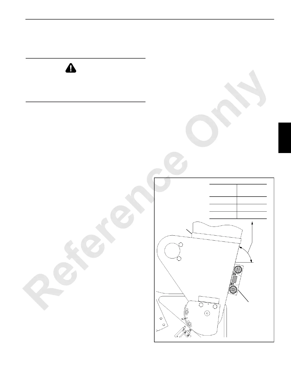
5. Verify that the boom is at the proper Angle A:
a. Place an accurate digital level (7) on the boom butt
as shown in Figure 4-2. The corresponding Digital
Level Angle should appear on the digital level.
b. Raise or lower the boom as necessary.
6. Check the position of the limit switch roller with relation
to actuator bracket (4, View B). If necessary, loosen the
limit switch mounting screws and adjust the limit switch
up or down in the mounting slots to obtain the dimension
in View B. Securely tighten the mounting screws.
Limit switch will not trip open if it is too far from
actuator bracket. Limit switch could be damaged
from over-travel if it is too close to actuator bracket.
7. Rotate actuator (3, View A) against the roller of limit
switch (2) until the limit switch just “clicks” open and
hold. The LED (if equipped) should go off when the
switch opens.
8. Securely tighten cap screws (5) to secure actuator (4).
9. Test the adjustment as follows:
a. Lower the boom several degrees below the
specified Angle A (LED comes on if equipped).
b. Slowly raise the boom.
c. Boom must stop at specified Angle A (LED goes
off if equipped); if the boom does not stop at the
specified angle:
- Stop raising the boom (move control handle to
off).
- Lower the boom several degrees below the
specified angle.
- Repeat adjustment steps 2 through 9.
10. Seal the adjustment as shown in Figure 4-1.
WARNING
Crush Hazard!
Maintain constant communication between operator and
assistant during following steps.
Stay clear of moving parts.
7
Against Left Inboard
Leg of Boom Butt
1
FIGURE 4-2
Boom
Angle
Digital Level
Angle
83° 76.5°
88° 81.5°
89° 82.5°

 Loading...


