BOOM 777 SERVICE MANUAL
4-2 Published 10-01-2012, Control # 045-08
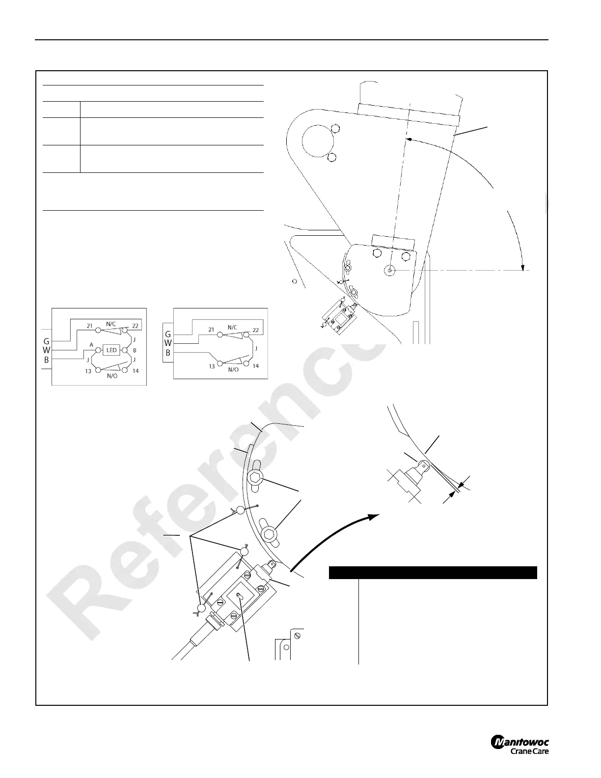
Horizontal
Centerline of
Boom
Left Inboard Leg of
Boom Butt
A
see Table
1
Angle A
83° #78 Boom.
88°
#78 Boom with #139 Luffing Jib when the
boom up limit can be bypassed.*
89°
#78 Boom with #139 Luffing Jib when the
boom up limit cannot be bypassed.*
*
To determine if the boom up limit on your crane can
be bypassed or not, perform Bypass Limit Test on
page 4-3.
Drill for 1/8 in (3,2 mm) dowel.
Install wire and seal lead after
adjustments are made.
VIEW A
(switch opened)
VIEW B
(switch closed)
3
4
5
1/16 in (1,59)
LED (past production)
OFF = Switch Open
ON = Switch Closed
2
6
4
2
Item Description
1Boom Butt
2 Limit Switch
3Actuator
4 Actuator Bracket
5 Cap Screw with Flat Washer and Lock Washer
6 Dowel Roll Pin with Seal Lead and Wire
7 Digital Level (see Figure 4-2)
FIGURE 4-1
LIMIT SWITCH WIRING
Past Production
N/C = Normally Closed
N/O = Normally Open
B = Black Wire
G = Green Wire
W = White Wire
J = Jumper Wire
Current Production
178715

 Loading...


