HYDRAULIC SYSTEM 777 SERVICE MANUAL
2-10 Published 10-01-2012, Control # 045-08
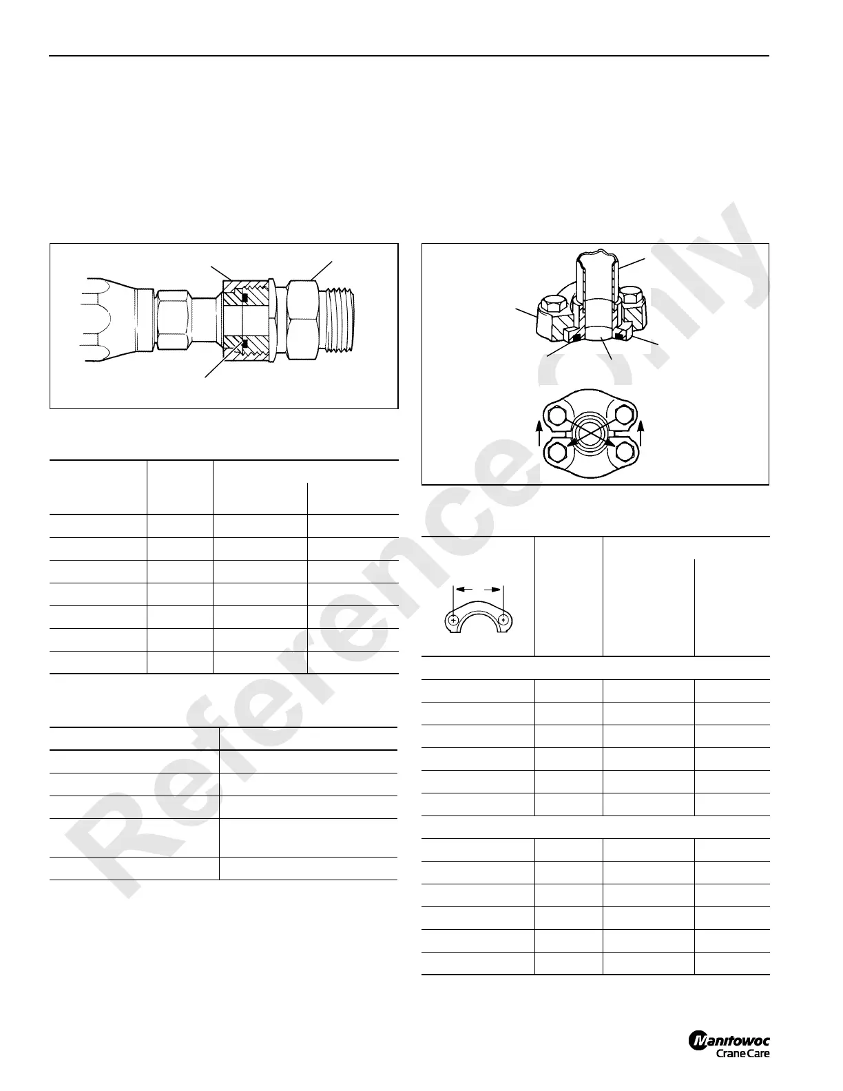
ORS Connection
NOTE: ORS is the registered trade mark for a face-type
seal manufactured by Aeroquip Corporation.
• Lubricate and install O-ring in adapter groove
(Figure 2-9).
• Lubricate threads.
• Tighten nut to torque value given in Table 2-4.
Table 2-4
ORS Assembly Torque
Table 2-5
ORS Leakage
Split Flange Connection
Lubricate and install O-ring in shoulder groove (see
Figure 2-10).
1. Align shoulder with port and assemble flanges over
shoulder.
2. Bolts used must be grade-5 or better. Grade-5 bolt has
three dashes in head.
3. Snug bolts in a diagonal manner (see Figure 2-10) to 1/3
of torque given in Table 2-6.
4. Repeat step 3 to 2/3 of final torque. Repeat step 3 to
final torque.
Table 2-6
Split Flange Assembly Torque
Nut Size
inch across
flats
Fitting
Size
Torque
in-lb Nm
5/8 -04 120 – 145 14 – 16
13/16 -06 203 – 245 23 – 28
15/16 -08 380 – 470 43 – 53
1-1/8 -10 550 – 680 62 – 77
1-3/8 -12 763 – 945 86 – 107
1-5/8 -16 1110 – 1260 125 – 142
1-7/8 -20 1500 – 1680 170 – 190
Causes Cures
Nut Loose. Tighten to proper torque.
O-ring cut. Replace.
O-ring wrong size. Replace with proper size.
Sealing surfaces gouged
or scratched.
Repair if possible or replace
damaged parts.
Sealing surfaces dirty. Clean and lubricate.
Nut
Adapter
O-Ring
FIGURE 2-9
S105
"A" Dimension
(inch)
Flange
Size
Torque
in-lb Nm
Standard Pressure Series
1-1/2 -08 175 – 225 20 – 25
1-7/8 -12 225 – 350 25 – 40
2-1/16 -16 325 – 425 37 – 48
2-5/16 -20 425 – 550 48 – 62
2-3/4 -24 550 – 700 62 – 79
3-1/16 -32 650 – 800 73 – 90
High Pressure Series
1-9/16 -08 175 – 225 20 – 25
2 -12 300 – 400 34 – 45
2-1/4 -16 500 – 600 57 – 68
2-5/8 -20 750 – 900 85 – 102
3-1/8 -24 1400 – 1600 158 – 181
3-13/16 -32 2400 – 2600 271 – 294
Port
Shoulder
Flange
O-Ring
FIGURE 2-10
S104
1
2
3
4
S101
Tube
A

 Loading...


