INTRODUCTION 777 SERVICE MANUAL
1-64 Published 10-01-2012, Control # 045-08
When luffing jib has been selected and confirmed at crane
mode selector, and rear drum park brake switch, located on
the front console in the operator’s cab, is placed in the off
position, the PC is prepared for any luffing commands
received from rear hoist control handle. With control handle
in the off position, the regulated voltage circuit for all luffing
commands to the PC remains open. Rear drum park brake
solenoid HS8 and rear drum band brake solenoid HS17 are
not energized and the rear hoist pump does not stroke until
the control handle is moved in either direction from off.
The description of all normal load handling operations with
the rear drum in luffing mode are identical to those described
for the front drum while performing liftcrane operations in full
power mode.
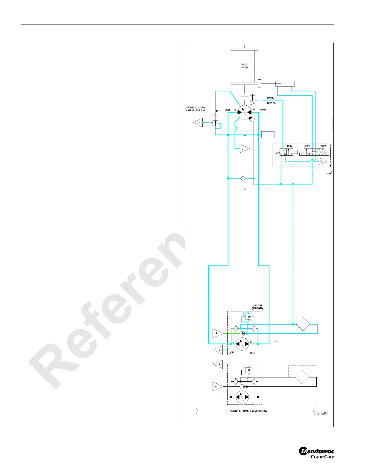
Auxiliary Hoist System
See Figures 1-46 and 1-47 for following procedures.
If crane has an auxiliary hoist, its drum is located in boom
butt.
Unlike all other system pumps, displacement in the auxiliary
hoist pump is controlled by both coils in the EDC valve and
function only with straight current rather than straight and
reverse polarity.
If auxiliary hoist charge pressure is lost for any reason,
auxiliary hoist park brake will apply to stop the hoist since the
brake is directly sourced from this pressure.
Like all other crane systems, the hydraulic connection
between auxiliary hoist pump and auxiliary hoist motor forms
a simple closed-loop circuit. Make-up oil from auxiliary hoist
charge pump replaces oil in the system that is primarily
displaced due to internal leakage of the pump and motor
assemblies.
If auxiliary drum park switch, located on the front console in
the operator’s cab, is placed in the on position, the auxiliary
hoist control handle circuit to the PC opens and does not
complete the circuit from the PC to auxiliary drum brake
hydraulic solenoid HS9. Because these circuits are open,
auxiliary drum park brake remains applied and auxiliary hoist
pump will not stroke in response to movement of auxiliary
hoist control handle.
The hydraulic actuation of auxiliary drum park brake is
spring-applied/pressure released and controlled
automatically by the PC in conjunction with movement of
auxiliary hoist control handle. Release of brake is with
auxiliary charge pressure and from low pressure side of its
closed-loop circuit through check valve.
When releasing brake, charge pressure is directed into
brake valve chamber through HS9. If the charge pressure
drops to below 250 psi (17 bar), brake application begins,
and if the pressure continues to drop to approximately 165
psi (11 bar) or lower, the brake is fully applied.
FIGURE 1-46

 Loading...


