INTRODUCTION 777 SERVICE MANUAL
1-26 Published 10-01-2012, Control # 045-08
Brake Release System
The load drum, travel, swing, and auxiliary hoist disc brakes
are hydraulically released. The load drums also have a
hydraulically released band-type brake.
Hydraulically Released
The PC automatically controls release of the load drum,
travel, and auxiliary hoist brakes once the selected system’s
park switch is placed in the off position and its control handle
is moved from off. The release of the swing brake is
controlled independently when the operator places the swing
brake switch in the off position.
When the rear load drum, travel, or swing, brake hydraulic
solenoid is energized, the applicable valve shifts to block the
tank port and to supply charge pressure from the rear drum
charge pump to the appropriate brake. The brake then
releases. The front load drum brake or auxiliary hoist is
released by pressure from their own system charge pump.
When a brake solenoid is de-energized, the valve closes to
block the pump port and to vent pressure in the brake to
tank. The brake then spring-applies.
If brake pressure or electric current is lost for any reason
during operation, the brakes will spring-apply to stop the
function.
Working Brakes (with free fall)
See Figure 1-17 for following procedures.
When in free fall, the operator can control the lowering of a
load by applying a linear force to the working brake pedal (4)
to control pressure to the working brake (band brake
cylinder) of the selected drum. The working brake pedal can
be described as a reverse modulating valve operating
between the system pressure of 2500 psi (no foot pressure
applied and in unlatched position) to 50 psi (maximum
applied foot pressure or in latched position).
The brake pressure is in direct proportion to brake pedal
movement. When applying manual force, with the foot to the
working brake pedal, a proportional amount of hydraulic
pressure is released from the band brake cylinder through
the working brake valve to tank, causing the release springs
of the cylinder to expand and apply brake band pressure
against the drum. When pedal is fully applied or latched full
brake application is obtained. Conversely, by releasing
manual force to the brake pedal, a proportional amount of
hydraulic pressure is applied to the brake band cylinder
causing the release springs to compress and remove brake
band pressure to the drum. When pedal is fully released, the
release spring is fully compressed, allowing the band brake
to be fully released.
The working brake section of the auxiliary systems pump
provides an adequate hydraulic fluid supply at a maximum
system pressure of 2,500 psi for band brake actuation. The
system flow pressure is controlled by relief valve preset to
2,500 psi (175 bar) and is regulated in pressure operating
range of 50 to 2,500 psi as it passes through the reverse
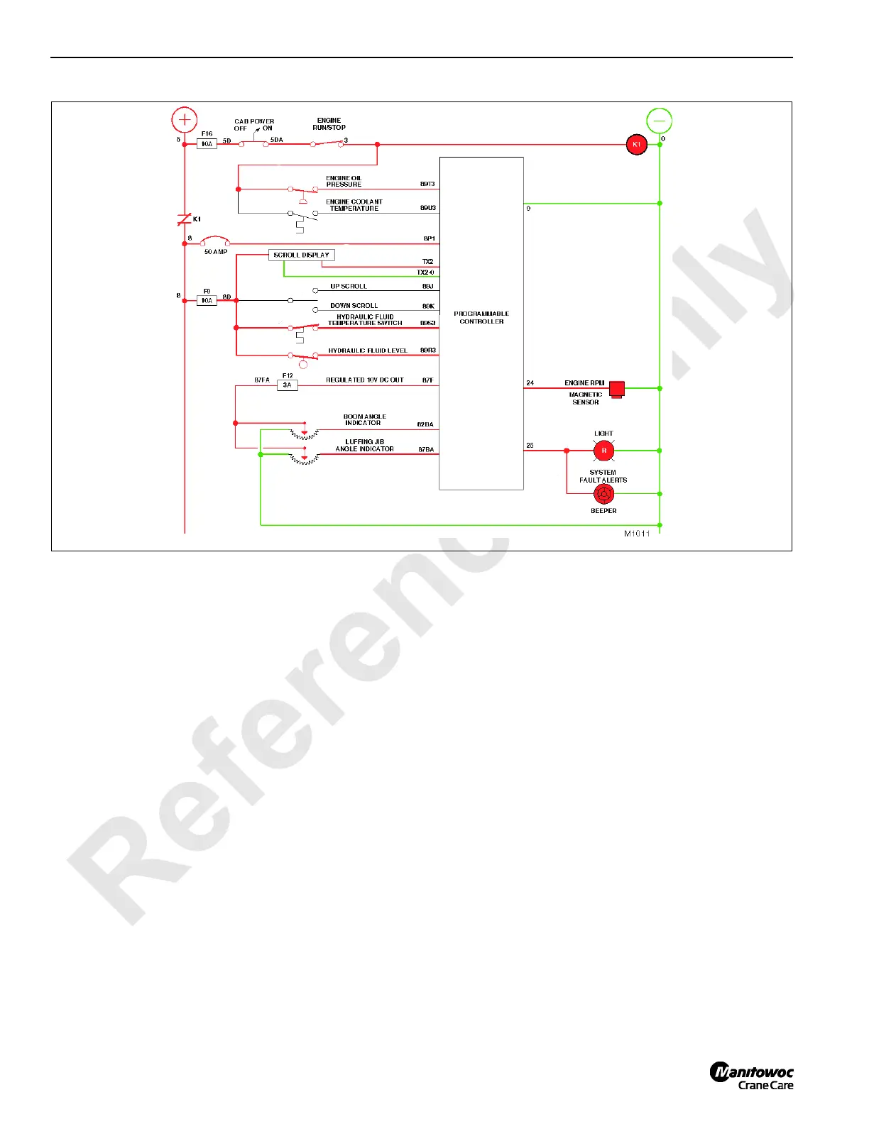
FIGURE 1-16

 Loading...


