Manitowoc Published 10-01-2012, Control # 045-08 7-5
777 SERVICE MANUAL POWER TRAIN
7
ENGINE CLUTCH ADJUSTMENT
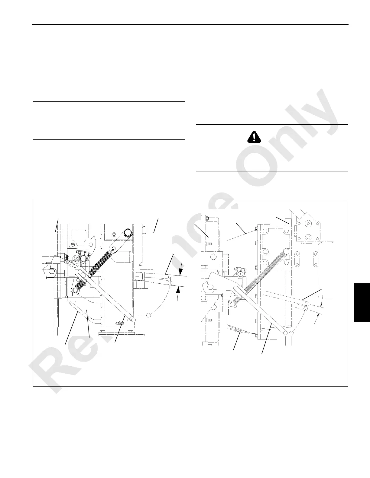
A disc-type manually operated clutch (see Figure 7-3) is
mounted between the engine and the pump drive on this
crane. The clutch allows the pump drive to be disconnected
from the engine, thereby reducing engine load and making
start-up easier in cold weather. The clutch can be engaged
or disengaged while the engine is running or off.
Operation
1. Grease the clutch monthly. See Lubrication in Section 9
of this manual.
2. At least once each month, disengage and engage the
clutch several times with the engine running. This
practice will clean the disc surfaces and prevent the
discs from seizing.
3. When disengaging the clutch, check free travel. Free
travel should be 1 to 1-1/8 in. (25 – 29 mm). Readjust the
clutch when free travel decreases to 3/4 in. (19 mm).
Adjustment
The clutch is adjusted internally through the hand hole on
bottom of the clutch housing. See the manufacturer’s manual
for adjustment instructions.
CAUTION
Parts Damage!
Do not run engine longer than 20 minutes with clutch
disengaged. Clutch release bearing can be damaged.
DANGER
Moving Machinery Hazard!
Parts inside clutch rotate when engine is running. Stop
engine before adjusting clutch.
Engine
Clutch
1 to 1-1/8 in
(25-29 mm)
Free Travel
Left Side of
Power Plant
Disengaged
Pump
Drive
FIGURE 7-3
A1000
Past Production
Hand Hole
Cover
Lock
Unlock
Engaged
Lock
Unlock
Current Production
A13392
Disengaged
1 to 1-1/16 in
(25-27 mm)
Free Travel
EngagedEngaged
Engaged
Pump
Drive
Engine
Clutch
Hand Hole
Cover

 Loading...


