BOOM 777 SERVICE MANUAL
4-20 Published 10-01-2012, Control # 045-08
End Lacing Replacement on an Insert (Angle and
Tubular Chords)
1. This procedure can be used for replacing the end lacing
on a top or butt lattice section with angle chords.
2. Pin another lattice section to the end of the section being
repaired. The connectors should be wedged over to
ensure no lateral movement.
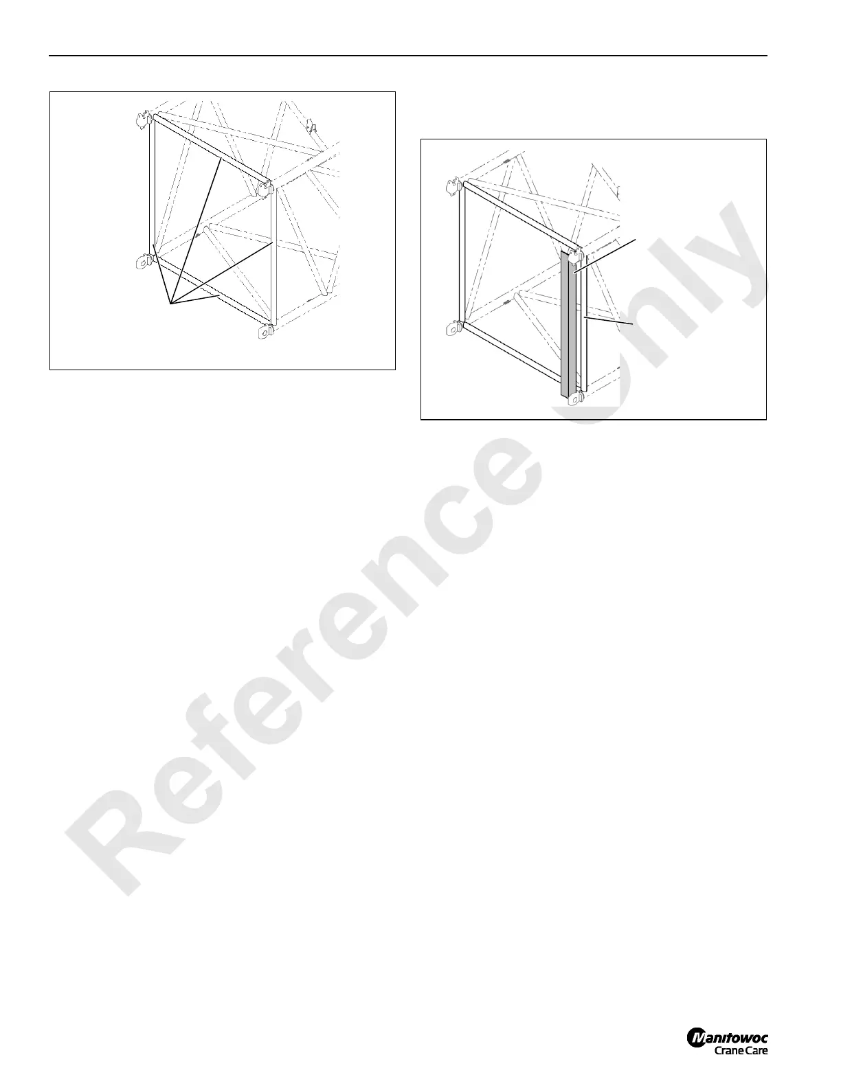
3. If another lattice section is not available, tack weld a
temporary brace to the connectors parallel to the
damaged lacing (see Figure 4-23).
Care must be taken to not damage the machined
surface of the connector.
• The temporary brace will need to be strong enough
to not allow the connectors to move in or out. A
minimum 4 in (102 mm) by 4 in (102 mm) by 3/8 in
(10 mm) angle is required.
• The connectors shall be preheated to a minimum of
150°F (66° C) before tacking.
• Use 3/32 in (2,5 mm) E9018-M stick electrode for
tacking the temporary brace.
• Tacks shall be 1 to 1-1/2 in (25 to 38 mm) long. The
tacks shall be sound with no undercut to the
connector.
• Do not tack to any machined surfaces.
4. Use the same process for removing and replacing lacing
as specified in Lacing Replacement on page page 4-18.
5. Remove the temporary bracing without damaging the
connectors.
Do not cut or gouge the connector. Stop all work if
connector is damaged and contact Manitowoc
Crane Care.
6. Send all completed inspection reports to Manitowoc
Crane Care. Digital photographs should be taken and
sent with the inspection reports.
End Lacing Replacement on Tapered Sections
(Tubular Chords)
1. This procedure applies specifically to tapered lattice
sections that have tubular chords. Examples: tops, butts,
and transition inserts.
2. The replacement end lacing cannot be installed into a
tapered lattice section due to clearance issues with the
connector. For this reason, the connectors cannot be
restrained to install the replacement lacing. Therefore
the section being repaired must be pinned to another
section.
3. Perform Lacing Replacement steps 1-7 on page
page 4-18. Do not replace more than one lacing at a
time.
4. The lacing must be installed and not tack welded.
Safety Note: Make sure the lacing cannot fall out and
injure someone.
5. Pin another lattice section to the end of the section being
repaired. The connectors should be wedged to prevent
lateral movement of the sections.
6. Only after the section is pinned to another section can
the replacement end lacing be tack welded into position.
7. Perform Lacing Replacement steps 8-14 starting on
page page 4-18.
8. Send all completed inspection reports to Manitowoc
Crane Care. Digital photographs should be taken and
sent with the inspection reports.
FIGURE 4-22
End Lacings
FIGURE 4-23
EXAMPLE
Damaged
End Lacings
Brace Tack Welded to
Connectors Parallel to
Damaged End Lacing

 Loading...


