Manitowoc Published 10-01-2012, Control # 045-08 8-3
777 SERVICE MANUAL UNDER CARRIAGE
8
Look for oil leaks, excessive wear, cracks, and other
damage. Broken or cracked parts can indicate that the
treads are adjusted too tight.
Repair or replace damaged parts immediately to prevent
further damage.
Tread Slack Adjustment
Adjustment Guideline
Check tread slack at the tumbler end of each crawler.
Maintain equal tread slack at both crawlers.
1. Travel forward or reverse on a firm level surface so all
tread slack is in top of treads at tumbler end of crawler.
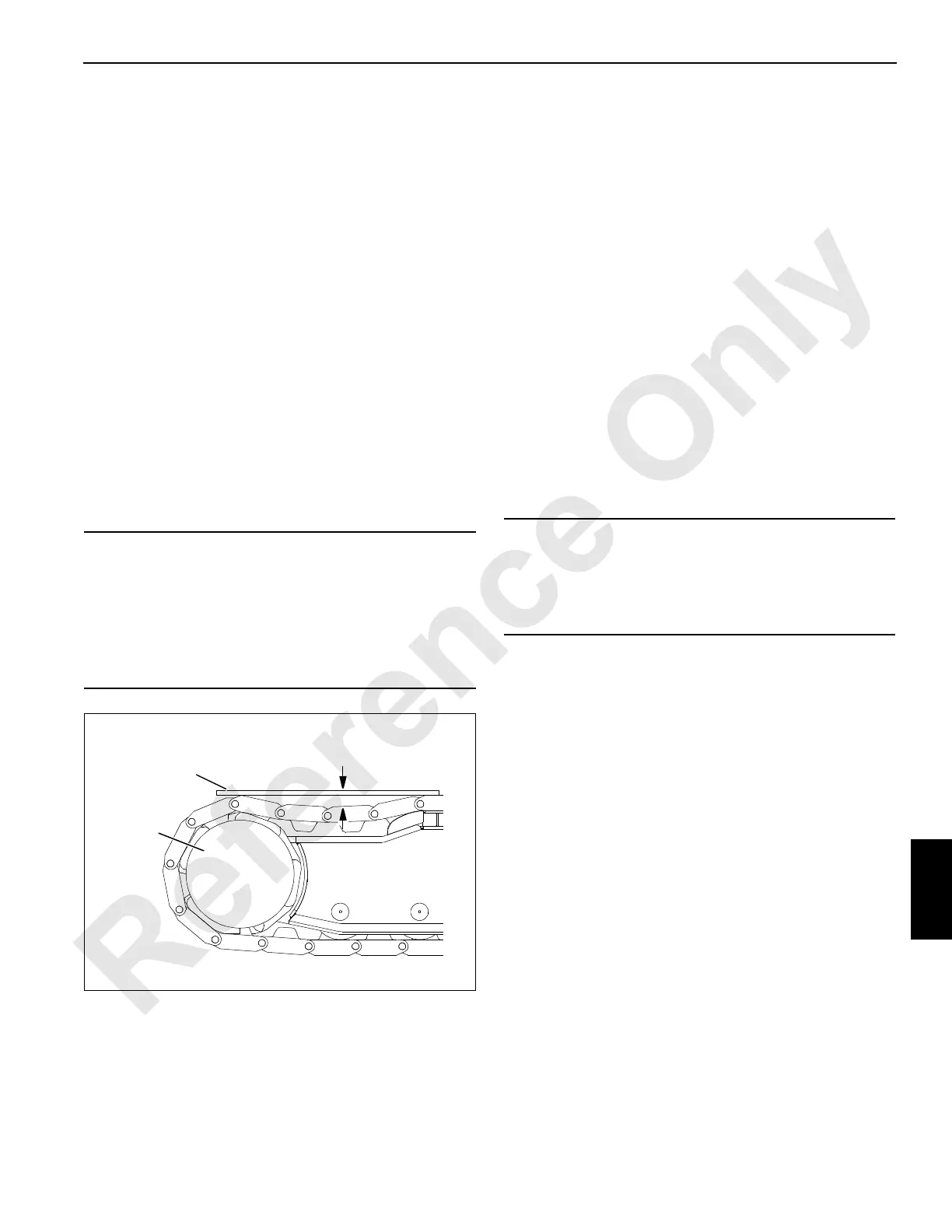
2. Place straight edge on treads as shown in Figure 8-2.
Gap between straight edge and top of treads at lowest
point should be 1 in. (25 mm) (tight limit) to 2-1/2 in.
(64 mm) (loose limit).
3. Adjust tread slack if gap exceeds loose limit or is less
than tight limit.
4. Adjust treads tighter when operating on firm ground and
looser when operating on soft ground (mud or sand).
Adjustment Procedure
Adjust tread slack at primary roller end of each crawler
(Figure 8-3):
1. Thoroughly clean crawler to be adjusted.
2. Loosen two bolts (1) at primary roller end of crawler
(1 bolt, each side).
3. Remove cover (2) from both sides of crawler frame.
4. Place jack cylinder (3) on support (4).
5. Jack against rod (5) an equal amount on both sides of
crawler frame.
6. Add or remove an equal thickness of shims (6) on both
sides of crawler frame.
7. Remove jack cylinder (3).
8. Travel crane forward to tighten shims.
9. Check that dimension from center punch (A) in shaft to
center punch line (B) in crawler frame is same on both
sides of crawler to within 1/8 in. (3.2 mm).
10. Check for proper adjustment (see Adjustment Guideline)
and readjust as required (steps 4 through 9).
11. Tighten nuts on bolts at primary roller to 1,000 ft-lb
(1 356 Nm) lubricate with Never-Seez or an equivalent
oil and graphite mixture.
12. Install cover (2) on both sides of crawler frame.
NOTE: The extreme limit of tread adjustment is when the
bolts are tight against the front end of the slots in
the crawler frame. One crawler tread should be
removed when this limit is reached.
CAUTION
Pin Damage!
Do not adjust treads too tight; tread pins will wear rapidly
and may break. Dirt build-up will tighten treads even
more, increasing possibility of damage.
More torque is required to drive tight treads, which results
in faster wear and more fuel consumption.
FIGURE 8-2
A972
Straight
Edge
1 in. (25 mm) Tight Limit
2-1/2 in. (33 mm) Loose Limit
Gap
Crawler
Tumbler
CAUTION
Part Wear!
Primary roller and tumbler must be square with crawler
frame to within 1/8 in. (3.2 mm); otherwise, parts will wear
rapidly.

 Loading...


