Manitowoc Published 10-01-2012, Control # 045-08 1-59
777 SERVICE MANUAL INTRODUCTION
1
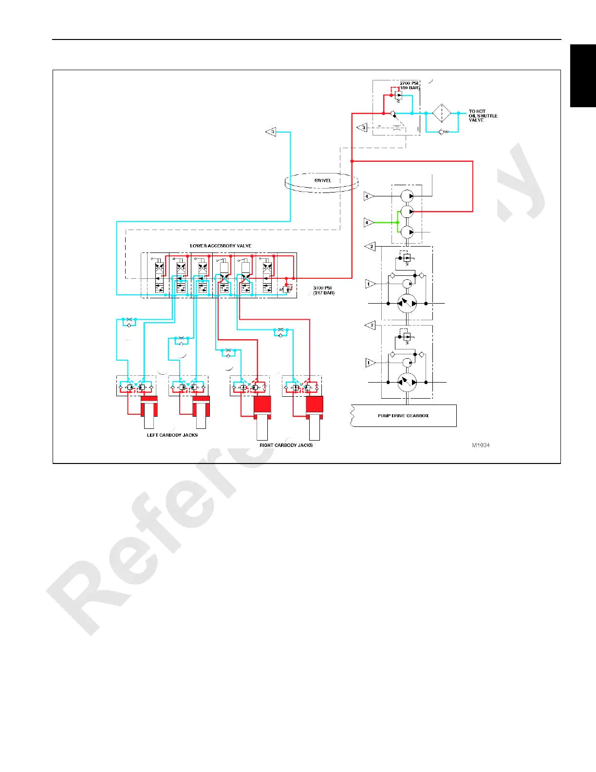
Jacking Cylinder Retract
See Figure 1-43 for following procedures.
When a jacking cylinder control valve handle is held in the
retract position, moving the lever upward on lower accessory
valve, the valve section shifts to direct oil flow from the setup
pump section of accessory pump and into relief valve (preset
to 3,100 psi / 214 bar) section of lower accessory valve. Note
the system pump flow pressure is limited by relief valve in
system disable valve which is preset to approximately 2,700
psi (186 bar).
The oil exits the desired function valve section of lower
accessory valve and flows through the restraining section of
flow control valve that controls the speed at which the
cylinder retracts by limiting the velocity of oil flow before
passing through the free-flow poppet (check valve) section of
counterbalance valve. The oil then proceeds into the rod end
of carbody jacking cylinder.
NOTE: Hydraulic pressure entrapped by the cylinder
counterbalance valve at the head end of the
carbody jacking cylinder supports the weight and
gravitational force of the carbody.
Oil exhausting from the head end of the carbody jacking
cylinder is blocked by the free-flow poppet (check valve)
section of counterbalance valve and flows through the
valve’s load restraining section which is preset to 3,500 psi
(241 bar). The counterbalance valve serves as a
deceleration control and functions with a 3:1 pilot ratio of the
pressure setting, permitting the valve to open when the
pressure in the rod end of the cylinder is approximately 1,170
psi (81 bar). The restraining section of counterbalance valve
opens which controls oil flow out of the carbody jacking
cylinder to lower accessory valve. The oil leaving the lower
accessory valve returns to tank.
FIGURE 1-41

 Loading...


