Manitowoc Published 10-01-2012, Control # 045-08 1-61
777 SERVICE MANUAL INTRODUCTION
1
Crawler Attachment System
The following description is for one set of crawler lock pin
cylinders. Operation of both sets of cylinders is identical.
Crawler Lock Pin Extend
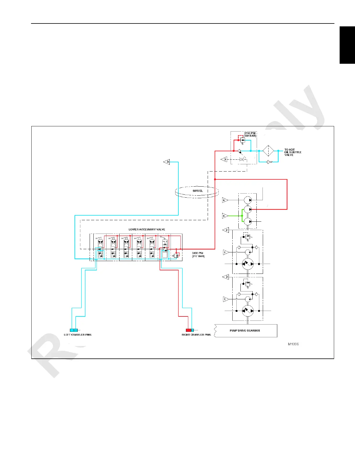
See Figure 1-43 for following procedures.
When a crawler lock pin control valve handle is held in the
extend position, moving the lever downward on lower
accessory valve, the valve section shifts to direct oil flow
from the setup pump section of accessory pump and into
relief valve (preset to 3,100 psi / 214 bar) section of lower
accessory valve. Note the system pump flow pressure is
limited by relief valve in system disable valve which is preset
to approximately 2,700 psi (186 bar).
The oil leaves the desired function valve section of lower
accessory valve and enters the head end of crawler lock pin
cylinders, causing the cylinder rod to extend, pushing
attachment pins into place, securing the crawler to the
carbody.
Oil exhausting from the rod end of crawler lock pin cylinder
returns to lower accessory valve and returns to tank.
FIGURE 1-43

 Loading...


