777 SERVICE MANUAL HYDRAULIC SYSTEM
Manitowoc Published 10-01-2012, Control # 045-08 2-29
2
Operating Pressure Checks
NOTE: It will be necessary to monitor pressure and pump
command on the diagnostic screens of the digital
display during the following steps. See Diagnostic
Display Readings in Section 10 of this manual. Do
not confuse pump command with handle command
on the display.
Electrical plugs must be disconnected at brake
solenoids (Figure 2-28).
1. Start and run engine at 1,000 – 1,400 rpm.
2. Select and confirm SETUP mode.
3. For each load drum, pull control handle back to check
pressure in hoist direction only.
Hoist pressure should be 6,000 psi (413.7 bar) when
pump command is less than 40%, and brake must not
slip.
4. For travel, move control handle in both directions, one at
a time, to check pressure in both directions.
Travel pressure in both directions should be 6,000 psi
(413.7 bar) when pump command is less than 40%, and
brake must not slip.
5. For swing, move control handle in both directions, one at
a time, to check pressure in both directions.
Swing pressure in both directions should be 4,900 psi
(337.9 bar) when pump command is less than 60%, and
brake must not slip.
6. Check boom hoist pressure by fully retracting boom
hoist cylinders (stall) until pressure reaches 5,000 psi
(344.8 bar). Pump command must be less than 40%.
7. Reconnect electrical plugs to all brake solenoids
(Figure 2-28).
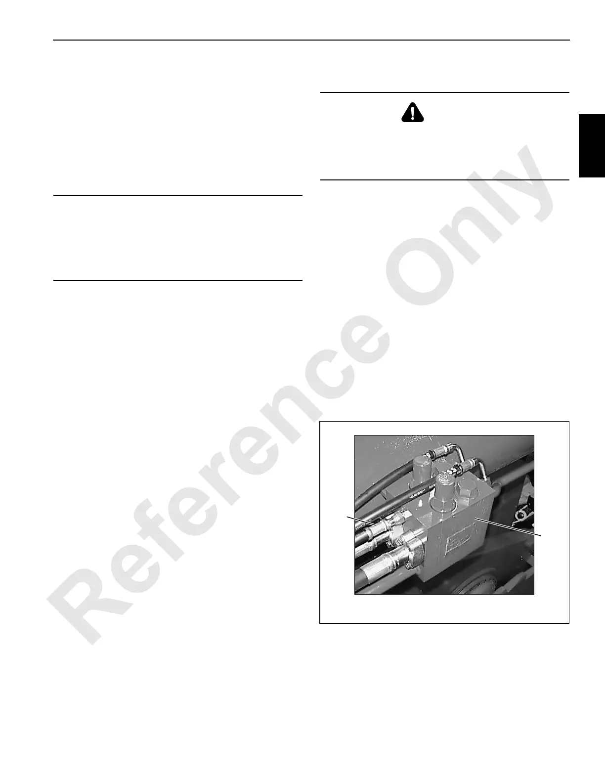
Boom Hoist Leakage Test
The following procedure requires a fully rigged boom with a
5,000 lb (2 268 kg) load suspended from boom point.
1. Stop engine.
2. Disconnect vent line from both cylinder valve blocks
(Figure 2-32).
3. Plug end of both hoses (08 ORS). Do not cap end of
adapter fittings (leave them open).
4. Start and run engine at high idle.
5. Check for oil leakage from both vent ports with boom
hoist in neutral and while raising and lowering boom.
Oil leakage in a five minute period must not exceed 1
drop per second. If leakage is greater than specified,
determine cause and correct.
6. Stop engine and securely reconnect vent lines to
adapter fittings. Make sure fittings are clean and O-rings
are installed.
CAUTION
Overheating Damage!
It is necessary to stall hydraulic system during following
pressure checks. Do not stall system longer than 10
seconds, or components may be damaged from
overheating
WARNING
Falling boom Hazard!
Only disconnect vent lines during following procedure.
Disconnecting any other line could cause boom to lower
uncontrolled.
FIGURE 2-32
Valve
Block
Left Side Cylinder Shown
(Right Side Similar)
Vent
Line
P984

 Loading...


