Manitowoc Published 10-01-2012, Control # 045-08 7-9
777 SERVICE MANUAL POWER TRAIN
7
Test Voltages
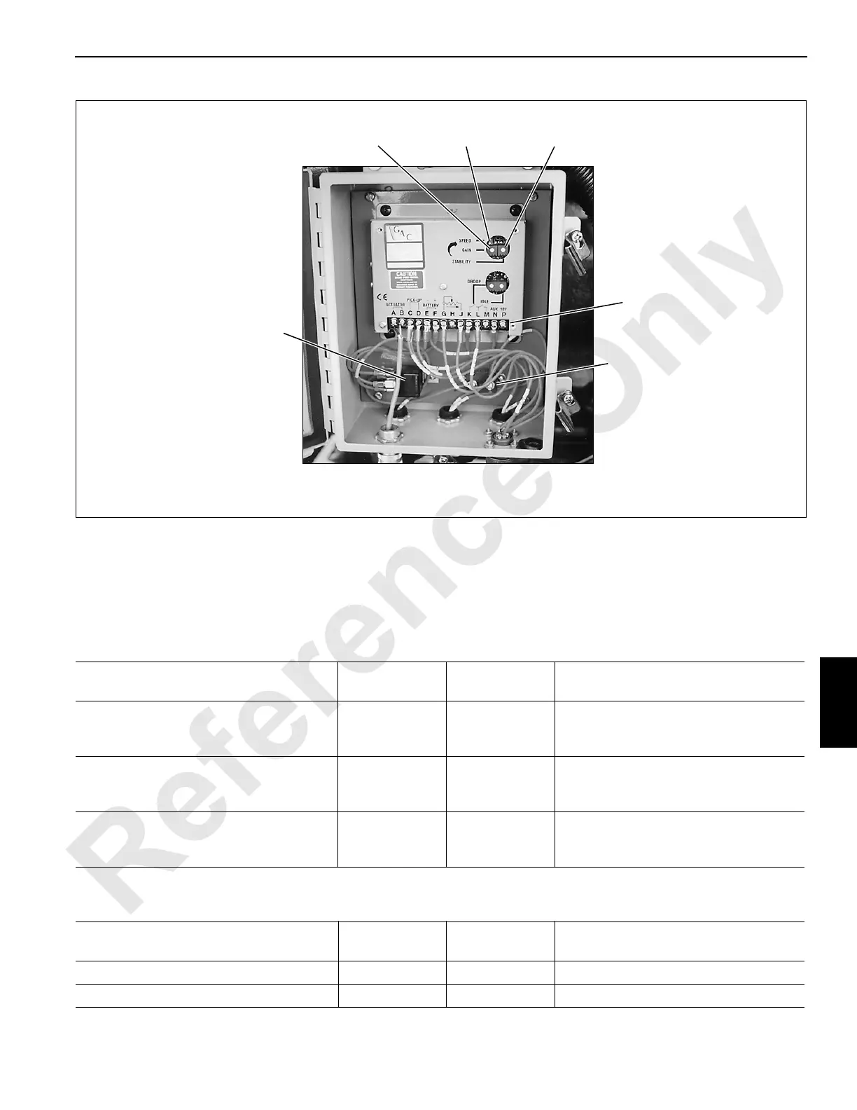
The following test voltages are provided for troubleshooting
purposes and are measured at the terminal strip in the
junction box on the engine (Figure 7-6).
Table 7-4
DC Voltage
Table 7-5
AC Voltage
FIGURE 7-6
Gain
Adjustment
P855
Speed
Adjustment
Stability
Adjustment
40 AMP
Relay
15 AMP
Circuit
Breaker
Junction Box on
Right Side of Engine
Te r m in a l
Strip
Operating Condition
Wire
Number
Terminal
Number
VDC Reading
All Readings to Ground
Cab Power Switch ON
Engine Run-Stop Switch in RUN
68L
68J
68K
G
J
L
0.005
5.880
3.848
Engine at Low Idle (1,000 rpm)
68L
68J
68K
G
J
L
0.007
5.870
3.812
Engine at High Idle (2,200 rpm)
68L
68J
68K
G
J
L
0.027
5.070
0.219
Operating Condition
Wire
Number
Terminal
Number VAC Reading
Engine at Low Idle (1,000 rpm) 24 and 0 C to D 6.580
Engine at High Idle (2,200 rpm) 24 and 0 C to D 7.480

 Loading...


