Manitowoc Published 10-01-2012, Control # 045-08 1-7
777 SERVICE MANUAL INTRODUCTION
1
GENERAL OPERATION
Operating System
A safety mechanism that prevents systems operation until
the cab seat is occupied by the operator, governs operation
of the EPIC® Hydraulic-Series crane. When the engine is
running and the operator is not seated, the seat switch circuit
is open, all control handles are inoperable, all park brakes
are applied (including free fall) and travel detent systems are
turned off. The display indicates an operating limit message
FUNCTION IS PARKED.
Hydraulic Components
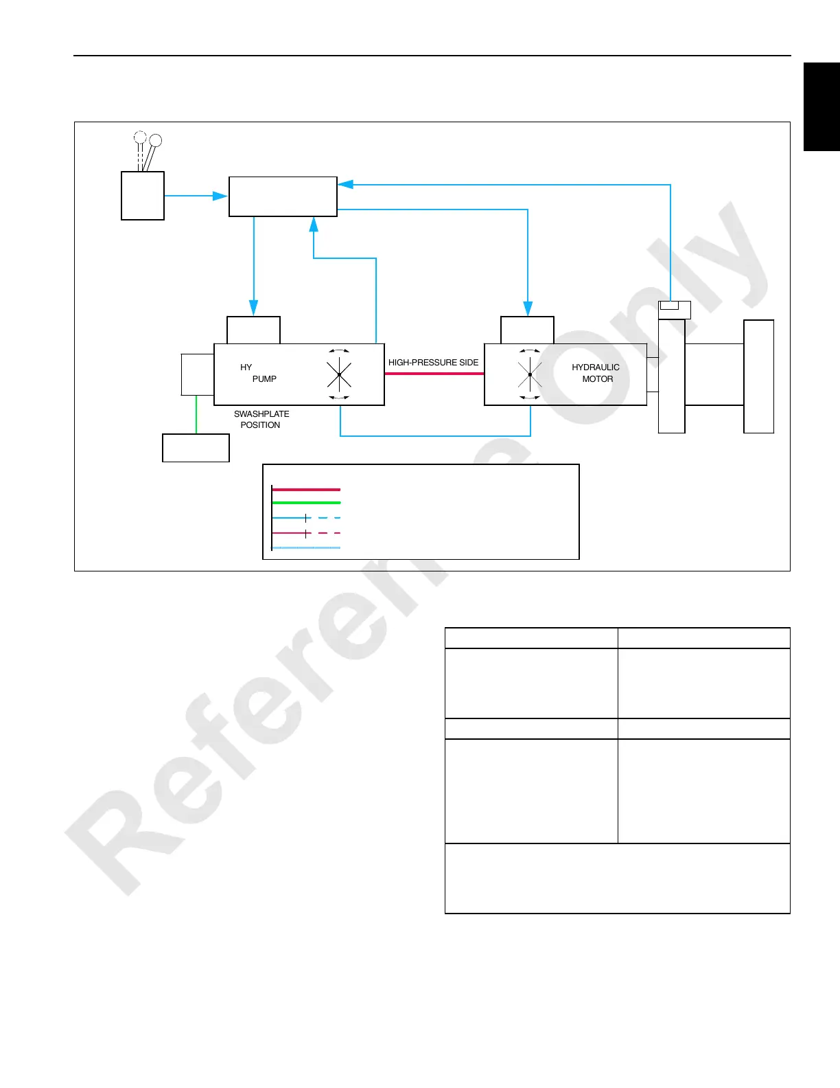
See Figure 1-4 for following procedure.
Each system is controlled through a programmable
controller (PC) and is independently powered by a hydraulic
pump and an actuator in a closed-loop hydraulic system.
See Table 1-1 for the types of pump and actuator in each
system, and to Sundstrand Series 90 Service Manual for an
operational description of a hydrostatic transmission.
In a closed-loop hydraulic system, the oil output from the
system pump drives an actuator, and then returns directly to
the pump’s input instead of returning to the crane’s hydraulic
tank.
Table 1-1
Pump and Actuator Description
A gear pump on each system pump supplies oil at charge
pressure to maintain the closed-loop system’s minimum
pressure requirements. This oil is also used to regulate the
oil flow from the pump by moving a swashplate
servomechanism within the pump in response to an external
electric displacement control (EDC).
FIGURE 1-4
COMMAND
SIGNAL
PILOT
CONTROL
PRESSURE
PCP
EDC
LINE LEGEND (FOR ALL SCHEMATICS)
CASE RETURN PRESSURE HYDRAULIC
CONTROL OR PILOT PRESSURE HYDRAULIC
LOW-PRESSURE HYDRAULIC, SIGNAL ELECTRICAL
NEGATIVE ELECTRICAL (GROUND), SUCTION MANAFOLD
HIGH-PRESSURE HYDRAULIC, POSITIVE ELECTRICAL
0000000000000000000000000000000000000000000000000000
POSITION
SWASHPLATE
HIGH-PRESSURE SIDE
MOTOR
HYDRAULIC
PUMP
HYDRAULIC
DRUM
CONTROLLER (PC)
MANIFOLD
SUCTION
PUMP
CHARGE
LOW-PRESSURE SIDE
FEEDBACK
FEEDBACK
PRESSURE
(MOTOR STROKE)
CONTROL SIGNAL
(PUMP STROKE)
CONTROL SIGNAL
CONTROL
DISPLACEMENT
ELECTRONIC
HANDLE
CONTROL
PIPING
HYDRAULIC
PROGRAMMABLE
HANDLE
RF-01
SPEED SENSOR
Pump System Description
Front and Rear Hoists (Load
Drums), Auxiliary Hoist,
Boom, Swing, and Travel.
Accessory
Variable Displacement, Axial
Piston
Fixed Displacement, Gear
Actuator System Description
Front and Rear Hoists (Load
Drums), Auxiliary Hoist,
Travel.
Boom Hoist
Swing
Variable Displacement, Bent-
Axial Piston Motor
Two Bi-Directional Cylinders
Fixed Displacement, Axial/
Piston Motor
Travel motors are normally in minimum displacement position
(low torque, high speed).
Travel motors start to shift to maximum displacement position
at approximately 3,500 psi (241 bar) (high torque, low speed).

 Loading...


