BOOM 777 SERVICE MANUAL
4-4 Published 10-01-2012, Control # 045-08
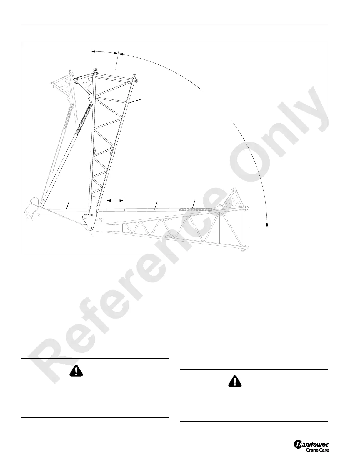
PHYSICAL BOOM STOP
The physical boom stop assembly (Figure 4-3) serves the
following functions:
• Assist in stopping the boom smoothly at any angle
above 81°.
• Assist in preventing the boom rigging from pulling the
boom back when traveling or setting loads with the
boom at any angle above 81°.
• Assist in moving the boom forward when lowering the
boom from any angle above 81°.
• Provide a physical stop at 90°.
Operation
See Figure 4-3 for following procedure.
1. When the boom is raised to 81°, the springs in the boom
stop tube begin to compress.
2. As the boom is raised higher, spring compression
increases to exert greater force against the boom.
3. If for any reason the boom is raised to 90°, the boom
stop springs will fully compress to provide a physical
stop.
Removal
Normally, the boom stop tubes are not removed unless they
need repair or replacement.
FIGURE 4-3
A991
81°
81° Start of
Spring Cushion.
Solid at 90°
32 inch
Overlap
Boom Stop
Upper Tube
Spring
Boom Stop
Lower Tube
Use care when handling boom
stop tubes. Lower tube is not
retained in upper tube.
Boom Butt
Shipping
Position
90°
WARNING
Falling Load Hazard!
Physical boom stop must be installed for all crane
operations. Physical boom stop does not automatically
stop boom at maximum operating angle. Automatic boom
stop must be installed and properly adjusted.
WARNING
Falling Load Hazard!
Use care if boom stop tubes are removed for any reason.
Lower tube is not retained by upper tube and they may
separate when detached.

 Loading...


