Manitowoc Published 10-01-2012, Control # 045-08 1-37
777 SERVICE MANUAL INTRODUCTION
1
The piston extends to detent location for the extend position,
disengages locking pins from slots concentrically located on
the shaft locking flange, permitting the crane to swing in
either direction after the parking brake is released. The
opposite function occurs when the swing lock switch is
placed in the engage position.
Off
See Figures 1-22 and 1-23 for following procedures.
When swing control handle is in the off position, the PC
opens a circuit to the swing pump EDC and swing pump
does not stroke. The rotating bed is free to coast if the swing
brake is released and the swing lock is disengaged.
During free coast, the PC maintains balanced pressure
between swing motor ports A and B to eliminate swing
movement even though the handle is not commanding
displacement.
Swing
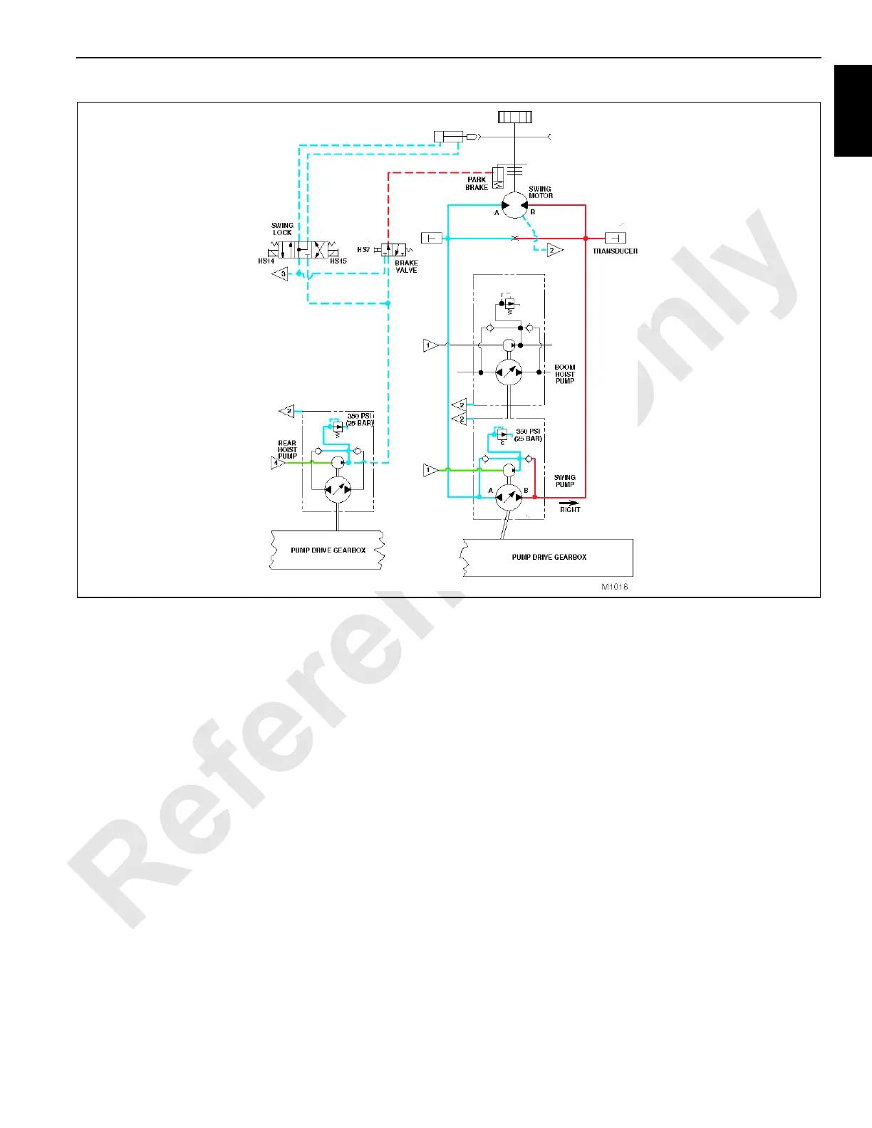
See Figures 1-22 and 1-23 for following procedures.
NOTE: The schematics show electric current flow to the
swing EDC and hydraulic oil flow to the motor for
swing right operation. The flows are opposite for
swing left operation.
When swing control handle is moved in either direction from
off, the handle neutral switch closes and a controlled
regulated variable voltage for an appropriate command is
sent to the PC. The PC provides corresponding voltage
direction and gain to the swing pump EDC. The PC tilts the
pump swashplate an amount that generates an oil
displacement output relative to handle movement.
When swing right is commanded, swing pump is stroked in
the appropriate direction so oil flows from pump port A to port
A of the swing motor, rotating the rotating bed in the
corresponding direction and desired speed.
The orifice across swing motor ports A and B, the low and
high sides of the hydraulic circuit, enables smoother oil flow
shifting when swinging from one direction to the other.
Pressure senders inform the PC of the pressure data
concerning both sides of the closed loop hydraulic circuit.
The PC uses this information to provide a free coasting effect
when swing control handle is returned to neutral and helps
provide a boom centering effect when picking loads to help
prevent side loading of the boom.
FIGURE 1-23

 Loading...


