Manitowoc Published 10-01-2012, Control # 045-08 1-63
777 SERVICE MANUAL INTRODUCTION
1
OPTIONAL SYSTEMS
Luffing Jib Hoist System
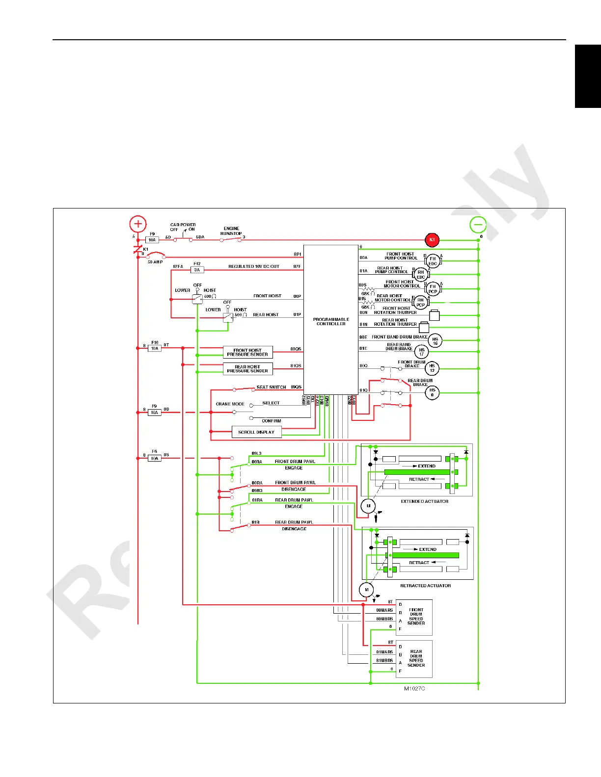
See Figure 1-46 for following procedures.
If crane has optional clutch assembly, the PC opens the
circuit to rear drum clutch hydraulic solenoid HS21 when
entering luffing jib mode. This ensures manifold oil is blocked
from entering the solenoid valve, and the valve’s exhaust
port is open to the drum clutch. The rear drum clutch remains
applied during the luffing function.
With optional clutch assembly, free fall switch must be closed
for brakes to release and pump to go on stroke.
In the luffing mode, the rear drum operates the luffing jib
while the front drum is the whip line. The front and rear
(luffing jib) hoist control handles are located adjacent to one
another on the right console in the operator’s cab.
If a BLOCK UP LIMIT or RCL operating fault occurs while
luffing, the PC will command the rear drum to stop lowering.
The corrective action for these operating faults is to raise the
jib. In full power mode corrective action requires lowering the
load with the rear drum.
FIGURE 1-45

 Loading...


