777 SERVICE MANUAL HYDRAULIC SYSTEM
Manitowoc Published 10-01-2012, Control # 045-08 2-3
2
3. Listen to pumps and motors for unusual noises; a high
pitched whine or scream can indicate that air is being
drawn in.
a. An air leak can be pinpointed by flooding inlet fitting,
hose, or tube with oil. If there is an air leak, the oil
will cause a noticeable reduction in noise.
b. Correct cause for any air leak, or pump/motor will be
ruined.
4. A high pitched whine or scream from the pump can also
indicate cavitation (pump being starved of oil). This
condition is caused by the following problems:
a. Plugged suction filter.
b. Collapsed or plugged suction line.
c. Wrong oil (viscosity too high).
5. Look for signs of overheating: heat peeled parts, burned
and scorched oil odor, and darkening and thickening of
oil. Maximum temperature of oil in tank must not exceed
180°F (82°C).
6. Have hydraulic oil analyzed at regular intervals to
determine condition of oil and extent of system
contamination.
By having the oil analyzed on a regular basis, an oil
change interval meeting your operating conditions can
be established.
Contact your oil supplier for the availability of oil analysis
services and the steps that should be taken to obtain
these services.
Servicing Pumps
It is not necessary to drain the hydraulic tank when servicing
the hydraulic pumps. To service the pumps, close the shut-
off valve (Figure 2-4, View C) in the pump suction manifold.
Open the valve before starting the engine after servicing the
pumps. The valve has a latch that allows the valve to be
locked open with a padlock installed.
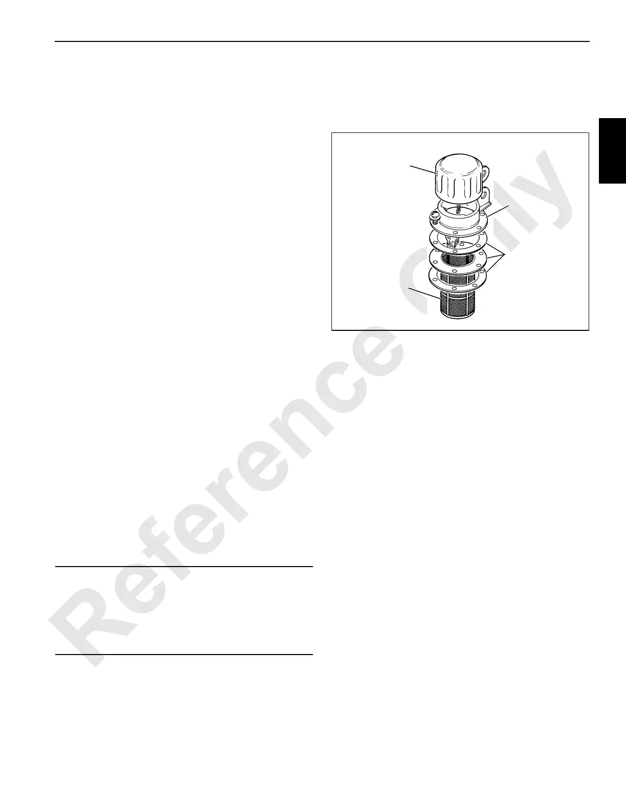
Cleaning Fill Cap Assembly
1. Clean fill cap monthly to ensure that ventilating ports in
fill cap remain open.
a. Clean area around fill cap assembly.
b. Remove fill cap from flange (see Figure 2-1).
c. Thoroughly clean fill cap with clean, nonflammable
solvent. Blow dry with compressed air.
d. Reattach fill cap to flange.
2. Clean entire fill cap assembly whenever hydraulic oil is
changed.
a. Clean area around fill cap assembly.
b. Disassemble fill cap assembly (see Figure 2-1).
c. Clean fill cap and screen in clean, nonflammable
solvent and blow dry with compressed air.
d. Replace screen if it is damaged.
e. Install new gaskets, if necessary.
f. Assemble screen, gaskets, and flange to tank;
tighten screws evenly.
g. Securely fasten fill cap to flange.
CAUTION
Avoid Damage to Pumps!
Open shut-off valve at hydraulic tank (Figure 2-4, View C)
and at Filter 1 (Figure 2-2, View B) before starting engine.
Failing to perform this step will cause damage to pumps
from cavitation.
S100
Gaskets
Flange
Screen
Fill Cap
FIGURE 2-1

 Loading...


