Manitowoc Published 10-01-2012, Control # 045-08 1-15
777 SERVICE MANUAL INTRODUCTION
1
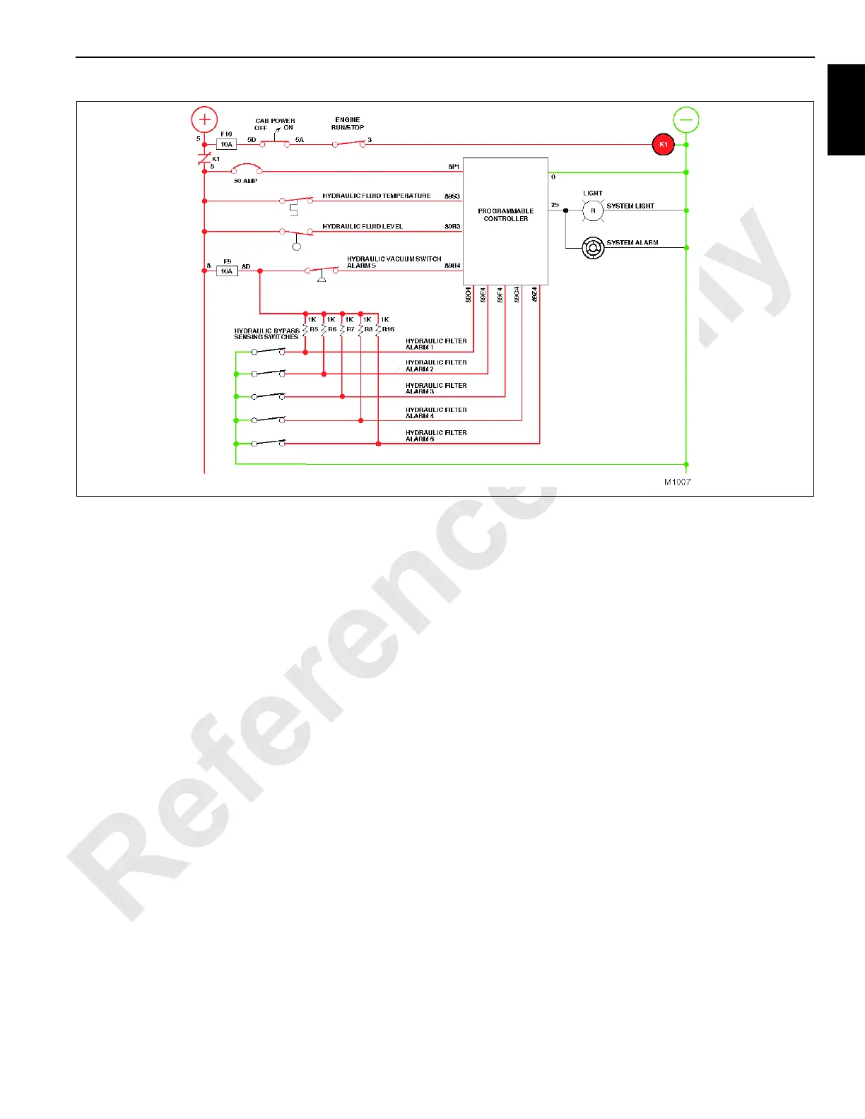
The front, rear, and auxiliary (optional) hoist pumps have
charge pressure filtration to meet the needs of each hoist’s
closed-loop circuit. In this method of filtration, charge pump
section of each pump (14) withdraws oil from the tank and
pumps it through a remote filter adapter into each filter (15)
to be processed. The oil is then routed back into the front,
rear, or auxiliary hoist pump through the remote filter
adapter. Note that the filter element contained in each filter
(15) has a rating of 13. As the element becomes soiled, the
pressure differential between the inlet and discharge flow
ports of the filter increases. When the filter 2, 3, or 6
hydraulic sensing switch on the filter head detects the
pressure differential to be 40 psi (2.8 bar), the switch closes
to complete the circuit to the PC. The PC responds by
sending a diagnostic message HYDRAULIC FILTER 2 for
front hoist, HYDRAULIC FILTER 3 for rear hoist, hydraulic
filter 6 for auxiliary drum) to the operator display, indicating
filter 2, 3, or 6 requires servicing, and activating fault system
light and fault system alarm. The affected filter must be
replaced at this time.
A supercharge filtration circuit supplies filtered oil to the
charge pumps of the boom, swing, and travel systems. This
circuit uses accessory pump (1) to withdraw oil from the tank
and deliver it at a pressure up to 75 psi (5 bar) through filter 1
and into supercharge manifold (16). The pressure differential
between the inlet and discharge flow ports of the filter
increases as the element becomes soiled, causing the filter 1
hydraulic sensing switch on the filter head to close and
complete the circuit to the PC. The PC responds by sending
a diagnostic message HYDRAULIC FILTER 1 to the operator
display, indicating filter 1 requires servicing, and activating
fault system light and fault system alarm. The filter must be
replaced at this time.
System filtration does not transform oil that has deteriorated
from prolonged use into a purified fluid. Factors affecting the
service life of hydraulic fluid include high operating
temperatures, excessive exposure to moisture or dust in the
work area, high concentrations of contaminant particles in
the oil, or admixtures to the oil of unlike viscosity or chemical
composition. A program to test or replace the hydraulic oil at
timely intervals should be established in order to ensure
efficient operation of the crane’s hydraulic system.
See the Lubrication Guide in Section 9 if this manual for
recommended replacement oil for the hydraulic system.
Suction Manifold
Supply oil to load drum and auxiliary hoist pumps (14) and
accessory pump (1) is obtained from suction manifold (17).
Suction manifold has a 3-inch service shut-off valve (18).
During hydraulic system maintenance operation, the valve
can be closed.
FIGURE 1-9

 Loading...


