HYDRAULIC SYSTEM 777 SERVICE MANUAL
2-28 Published 10-01-2012, Control # 045-08
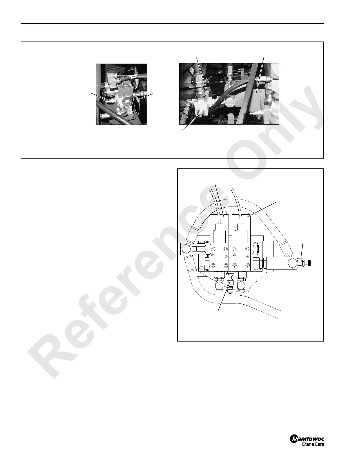
Band Brake Relief Valve Pressure Check
1. Connect a 0 – 5,000 psi (0 – 344.8 bar) pressure gauge
to coupler at band brake relief valve (Figure 2-30).
2. Start and run engine at low idle. Gauge must read 2,400
– 2,600 psi (165.5 – 179.3 bar).
3. If proper pressure is not obtained, turn relief valve screw
in to increase pressure or out to decrease pressure.
4. Tighten nut on screw to lock adjustment.
5. Stop engine and remove gauge from coupler. Install dust
cap over coupler.
Drum Clutch Pressure Adjustment
Perform following procedure only if crane has free fall.
1. Connect a 0 – 5,000 psi (0 – 344.8 bar) pressure gauge
to coupler at drum clutch pressure reducing valve
(Figure 2-31).
2. Start and run engine at low idle.
3. Turn adjusting screw in to increase pressure until gauge
reads 1,200 – 1,300 psi (82.7 – 89.6 bar).
4. Tighten nut on screw to lock adjustment.
5. Stop engine and remove gauge from coupler. Install dust
cap over coupler.
P571
Right Side of Crane
Behind Rear Drum
When Crane does
not have Free Fall.
P578
Left Side of Pumps When
Crane has Free Fall
Gauge
Coupler
Band Brake
Relief Valve
Gauge Coupler
(behind)
Supercharge and
Accessory Pump
Band Brake
Relief Valve
FIGURE 2-30
FIGURE 2-31
Rear Drum Clutch
Solenoid Valve
Pressure
Reducing
Valve
Gauge
Coupler
A1103
Front Drum Clutch
Solenoid Valve
Located in Right Enclosure
Between Drum Drives

 Loading...


