Manitowoc Published 10-01-2012, Control # 045-08 10-35
777 SERVICE MANUAL TROUBLESHOOTING
10
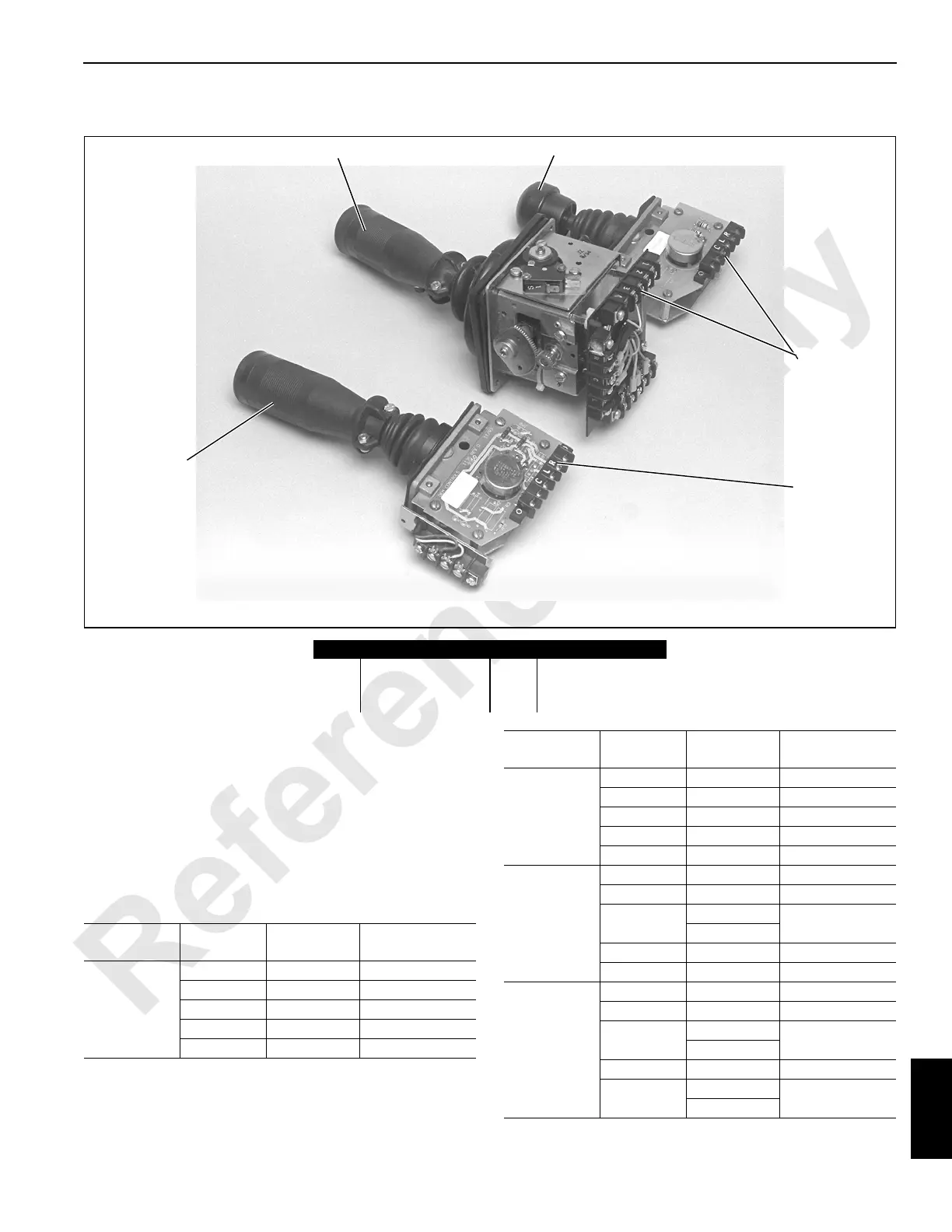
Test 7 – Checking Voltage at the Control Handle
Use the following test points to determine if the correct
voltages are present at the desired control handle. With
engine off/power on, and all brakes and locks engaged,
move the desired control handle and measure the voltage
with a digital multimeter. The positive probe must be placed
on the test terminal and the negative probe on a grounded
component or terminal R on the control handle. Voltages
outside the normal range may indicate a problem with the
control handle, its circuits, or in line components such as
relays and fuses.
Item Description Item Description
1 Load drum handle 4 Test terminals
2 Boom/swing handle 5 Ground terminal R
3 Crawler handle
2
1
AA318
3
4
5
FIGURE 10-9
Hand
Controller
Test
Terminal
Wire No.
Acceptable
Voltage (VDC)
Swing
L 87FA 10
R 0 Ground
C 85P 1.7 to 8.3
38D 12
4 89B2 12
Boom
Cylinder
L 87FA 10
R 0 Ground
C 82P 1.4 to 8.6
1 0 Ground
2 82N 12
Travel
L 87FA 10
R 0 Ground
C
83P (Right)
1.4 to 8.6
84P (Left)
38D 12
4 89X 12
Load Drum
L 87FA 10
R 0 Ground
C
80P (Front)
1.4 to 8.6
81P (Rear)
1 0 Ground
2
80N (Front)
12
81N (Rear)
Hand
Controller
Test
Terminal
Wire No.
Acceptable
Voltage (VDC)

 Loading...


