HYDRAULIC SYSTEM 777 SERVICE MANUAL
2-24 Published 10-01-2012, Control # 045-08
Initial Start-Up
1. Calibrate pressure transducers, if not already done.
2. Before starting engine first time with free fall,
remove adjusting screw from drum clutch pressure
reducing valve (Figure 2-31). Then reinstall screw 1/4 in.
(6 mm). The pressure reducing valve will be adjusted
later in this procedure.
3. Connect a 0 – 500 psi (0 – 34.5 bar) hydraulic gauge to
coupler at supercharge relief valve (Figure 2-26).
4. Loosen nut. Turn supercharge relief valve screw out fully
to stop (counterclockwise) (Figure 2-26).
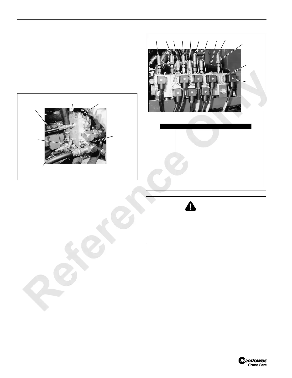
5. Connect bleed lines with shut-off valves to couplers on
pressure sender manifold (Figure 2-27). Open valve on
each bleed line. Use a suitable container to catch oil
flow.
P577
Accessory System
Pilot Check Valve
Under Left
Side of Pumps
Supercharge
Gauge Coupler
(behind)
Accessory System
Relief Valve
Supercharge
Relief Valve
Supercharge
and Accessory
Pump
Accessory
System
Gauge
Coupler
FIGURE 2-26
WARNING
Personal Injury Hazard!
With engine running, crane components can operate
unexpectedly while system pressures are checked and
adjusted. Disconnect power to brake valves before
beginning adjustments.
FIGURE 2-27
Item Description
1 Left Track Forward/Reverse
2 Right Track Forward/Reverse
3 Swing Left
4 Swing Right
5 Boom Hoist Cylinder (Boom Up)
6 Boom Hoist Pump (Boom Up)
7 Front Load Drum (Hoist)
8 Rear Load Drum (Hoist)
9 Auxiliary Load Drum (Hoist) (optional)
Gauge Coupler
(typical)
P697
298765431
Electric
Plug
(typical)
Pressure
Sender
(typical)
Left Side of Pumps

 Loading...


