BOOM 777 SERVICE MANUAL
4-6 Published 10-01-2012, Control # 045-08
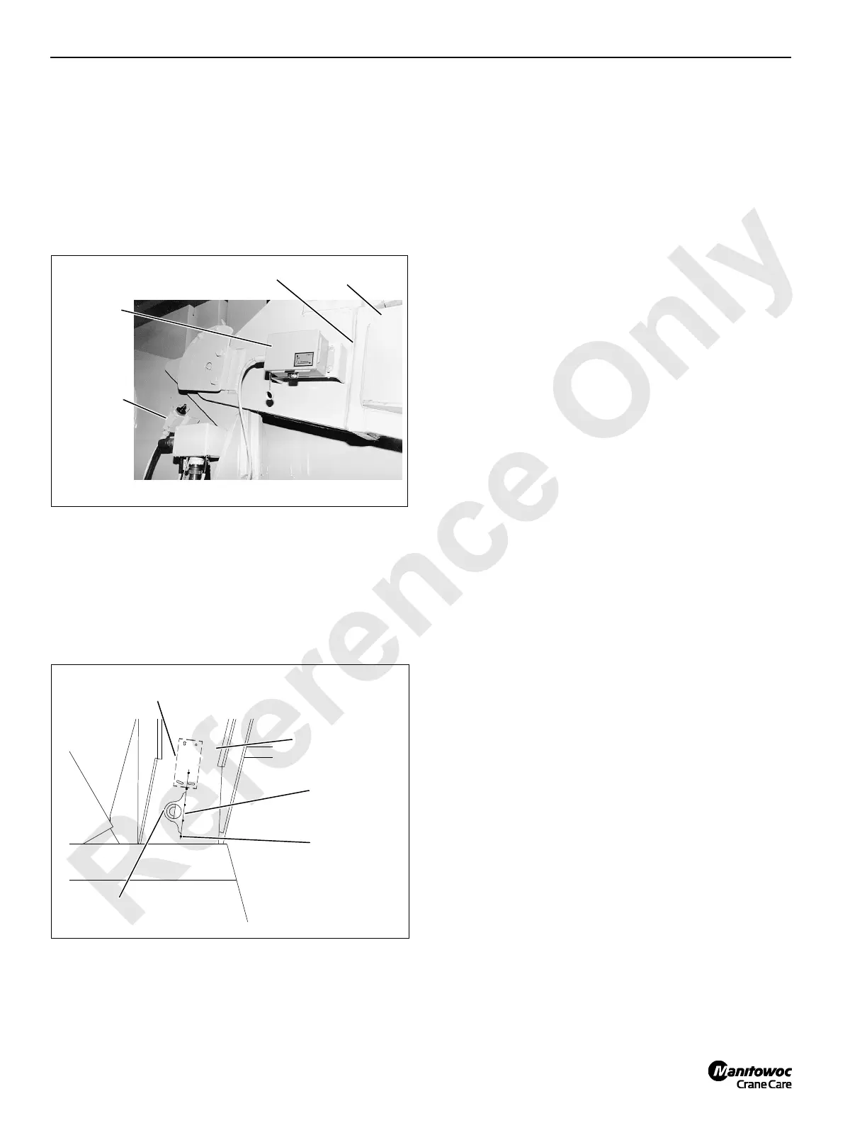
BOOM ANGLE INDICATOR
An angle sending unit mounted on the boom butt
(Figure 4-4) monitors the boom angle.
The sending unit houses a sensor which sends an electric
signal to the crane’s programmable controller. The
programmable controller converts the electric signal into an
angle which can be monitored on the digital display in the
operator’s cab.
Adjusting Angle Indicator
Perform following adjustment steps at initial installation, after
installing a new sending unit or potentiometer, and at least
monthly when boom is lowered to ground (Figure 4-5).
1. Locate punch marks on line through centerline of boom
butt as shown in Figure 4-5. If necessary, scribe a line
through punch marks.
2. Hold a protractor-level along scribed line.
3. Record angle indicated on protractor-level.
4. Scroll to boom angle on digital display in operator’s cab.
5. Angle shown on digital display must match angle
recorded in step 3 plus or minus one degree.
6. If necessary, loosen mounting screws and rotate
sending unit in mounting slots until reading on digital
display matches angle on protractor-level.
7. Securely tighten mounting screws to lock adjustment.
Sensor Replacement
Replacement sending units can be either the pendulum-type
120° potentiometer (past production) or solid state sensor
(current production).
Pendulum-Type 120°
Potentiometer
When replacing parts in the pendulum-type potentiometer
sending unit, take the following precautions (see Figure 4-6,
View A):
Mount potentiometer at angle shown.
Connect black, green, and white wires from receptacle to
proper terminals on terminal strip.
Connect wires from potentiometer to proper terminals on
terminal strip.
Make sure all parts are securely fastened to their mounting
position.
Solid State Sensor
When replacing existing pendulum-type potentiometer with
current production solid state sensor, take the following
precautions (see Figure 4-6, View B):
Identify all input wires to existing potentiometer.
Cut existing input wires near terminal strip (if used) to allow
for splicing.
Remove existing potentiometer and terminal strip (if used).
Mount new sensor in existing holes at 52.5° as shown in
View B.
Refer to wiring chart in View B and parallel splice sensor
wires to existing input wires with crimp, solder, and heat
shrink tubing.
Seal green wire on sensor with heat shrink tubing and coil
up.
Angle Sending Unit
Boom Butt
(left inboard leg)
Boom Stop
Limit Switch
Receptacle
FIGURE 4-4
P437
Punch Mark
(typical)
Scribed Line
Boom Butt
(right outboard leg)
Protractor
Level
Angle Sending Unit
(left inboard leg)
FIGURE 4-5
A990

 Loading...


