Manitowoc Published 10-01-2012, Control # 045-08 7-11
777 SERVICE MANUAL POWER TRAIN
7
ENGINE THROTTLE ADJUSTMENT -
CUMMINS QSL 340, QSC8.3, QSM11, OR
QSX15 ENGINE
The throttle assembly for the Cummins QSL 340, QSC8.3,
QSM11, and QSX15 engines consists of an electronic
control module (ECM) on the engine, a hand throttle
controller in the left console, a foot pedal on the cab floor, a
foot throttle controller in the right console, associated
linkage, and electrical connections.
A reach rod in the right console connects the foot pedal to
the lever on the foot throttle controller. An electric cable
connects the foot throttle controller in the right console to the
hand throttle controller in the left console.
Foot Throttle Linkage Adjustment
See Figure 7-4 for following procedure.
1. Install spring clip (1) and rod end (2) on controller lever
at dimension shown in View A and securely tighten jam
nut (3).
2. Insert a 3/16 in. (5 mm) thick shim or piece of floor mat
between foot pedal and cab floor.
3. Press foot pedal down fully to HIGH IDLE position
against shim or floor mat.
4. Adjust reach rod (4) and rod end (5) so controller lever is
rotated fully to HIGH IDLE position. Securely tighten jam
nuts (6) to lock adjustment.
NOTE: Controllers have internal stops at high and low idle.
5. Release foot pedal to low idle position.
6. Adjust return springs so there is sufficient force to raise
pedal and rotate controller lever to low idle.
7. Adjust pedal stop screw (7). Screw must be tight against
cab floor and there must be 1/8 in. (31 mm) gap between
pin (9) and rear end of slot in rod end (5). Securely
tighten jam nut (8).
8. With foot pedal in LOW IDLE position, distance from top
of pedal to cab floor should be 3-15/16 in. (100 mm).
Engine Speed Calibration
Engine speed is calibrated automatically by the crane’s
programmable controller:
• High idle = 2,100 rpm (QSL 340 = 1,800 rpm)
• Low idle = 1,000 rpm
Wiring Diagram
For a wiring diagram of the system, see Electrical Operator’s
Cab Wiring drawing in your Parts Manual.
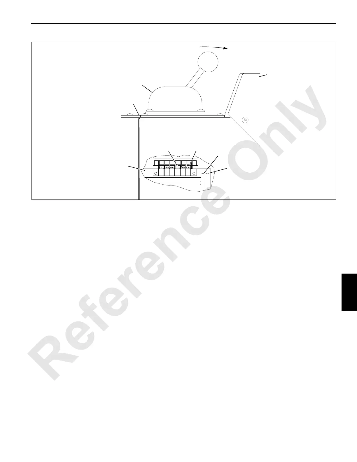
FIGURE 7-7
Cover
Converter
Board
Threshold
Potentiometer
Left
Console
Span
Potentiometer
Hand
Throttle
Controller
0
68K
A974
Low Idle

 Loading...


