INTRODUCTION 777 SERVICE MANUAL
1-46 Published 10-01-2012, Control # 045-08
increased as the control handle is moved farther backward,
pumping more oil to the motor and raising the load faster.
As control handle approaches the full handle command
position, and if lifting conditions permit, the PC instructs the
front hoist motor PCP valve to shift in proportion to handle
position and redirect oil flow to motor servo cylinder This
allows the servo mechanism to shift the motor gradually
forward to a minimum displacement for maximum motor
speed at less operating torque.
As control handle is returned to the off position, the PC
commands the front hoist pump EDC to decrease the angle
of the pump swashplate, causing a reduction in oil flow
output. The PC also instructs the front hoist motor PCP valve
to shift, in proportion to handle position, the front hoist motor
to maximum displacement for slower output speed to slow
the drum rotation. When the control handle is fully off, the PC
memorizes the pressure required to support the load and de-
energizes HS12 and HS16 to apply the brakes after the
control handle neutral switch opens or after receiving a zero
command from front drum speed sender.
Lower
See Figures 1-33, 1-34, and 1-35 for following procedures.
When front hoist control handle is pushed forward for down
operation, the handle neutral switch closes, completing a
regulated voltage circuit from the handle potentiometer to the
PC. The PC interprets the signal for speed and direction and
closes regulated polarity voltage circuit to the front hoist
pump EDC, a regulated voltage to front hoist motor PCP, and
front drum disc brake solenoid HS12. These circuits close
only if seat switch is closed, free fall switch, the front drum
park switch is off, the front drum pawl switch is disengaged,
applicable operating limit switches are closed and no system
or operating faults are present.
PC programming requires front hoist pump, to stroke
momentarily in the hoisting direction to reach memorized
load holding pressure before the front band brake is
released. This ensures adequate pressure is present to hold
the load after full release of the band brake. Front hoist
pressure sender, supplies the PC with pressure
development data which the PC compares to the memorized
holding pressure of the front hoist. When adequate pressure
is available, the PC energizes HS16 shifting the brake valve.
This initiates full release of band brake, front drum brake and
front hoist motor lowers the load. A regulated reverse polarity
voltage to the front hoist pump EDC then tilts the pump
swashplate to stroke the pump in the down direction. Oil then
flows from pump port B to port B of front hoist motor.
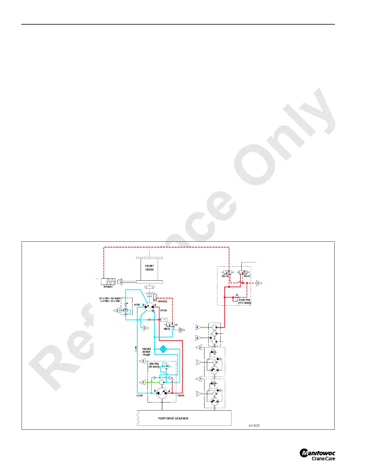
FIGURE 1-32

 Loading...


